206
35. CHECKS AND ADJUSTMENTS
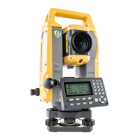
6. When the laser beam is on the upper (lower) part of Fig. A
the up/down adjustment is made as follows:
(1) Insert the provided hexagon key wrench into both the
upper and lower screws.
(2) Slightly loosen the upper (lower) screw and tighten the
lower (upper) screw. Make sure that the tightening
tension for both screws is identical. Continue to adjust
until the laser beam is on the horizontal line of the target.
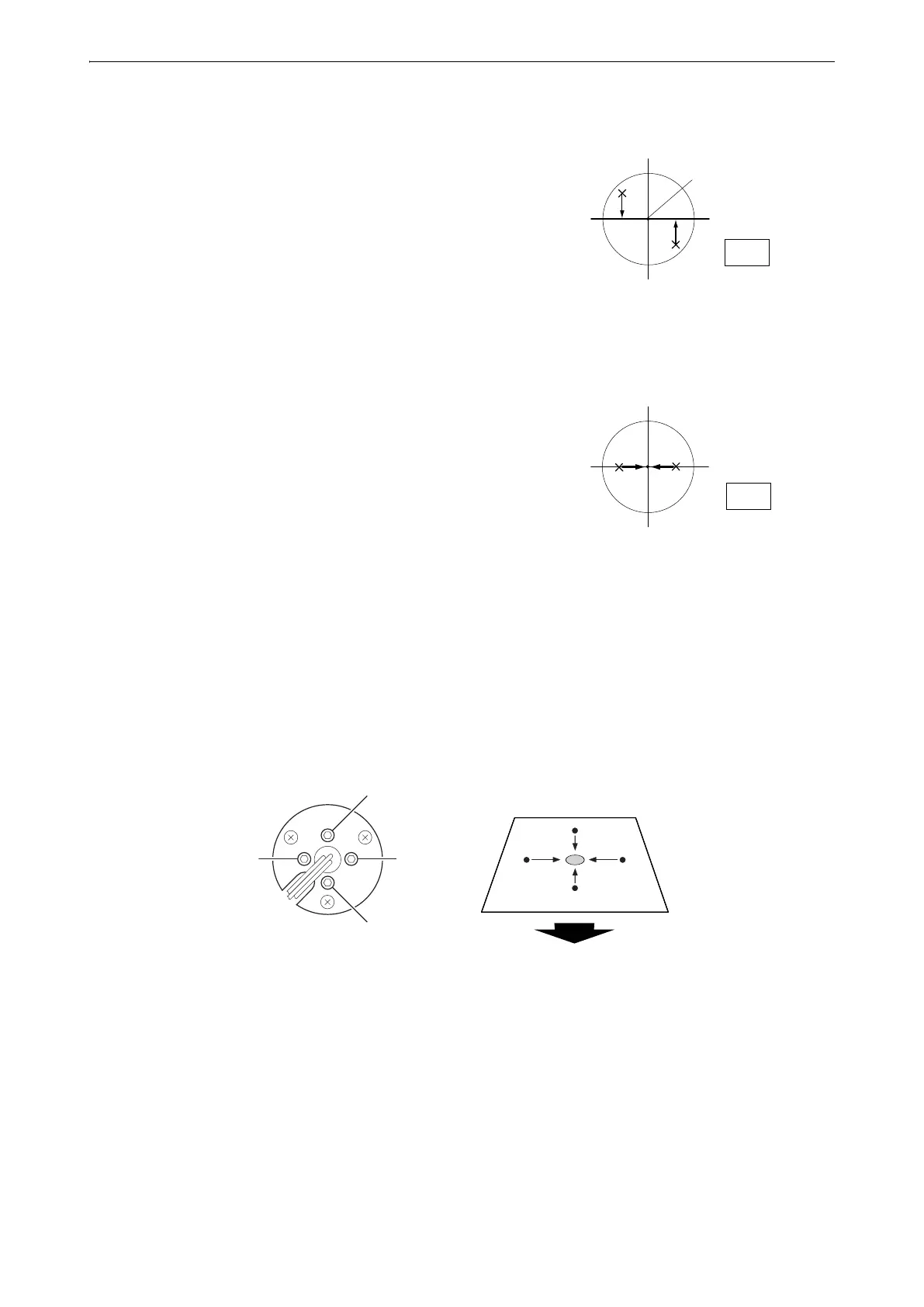
7. When the laser beam is in the right (left) part of Fig. B the
left (right) adjustment is made as follows:
(1) Insert a hexagon key wrench into both the left and right
screws.
(2) Slightly loosen the right (left) screw and tighten the left
(right) screw. Make sure that the tightening tension for
both screws is identical.
Continue to adjust until the laser beam is aligned with the
target center.
8. Turn the upper part of the instrument horizontally and check
that the laser beam is now aligned with the target center.
9. Re-attach the laser plummet adjustment cap.
• Tightening each of the fine adjustment screws moves the laser plummet beam in the directions shown below.
Fig. A
Desired final position
Fig. B
Up
Right
Left
Down
Tighten "Up" screw
Tighten "Right"
screw
Tighten "Down" screw
Tighten "Left"
screw
Fine adjustment screws
Laser plummet adjustment cap
pointing towards user
 Loading...