External Connectors
2-9
P/N: 1023998-01
Getting Acquainted
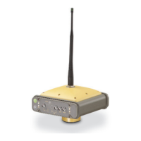
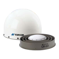
Figure 2-10: A BNC Connector is used for the UHF Modem
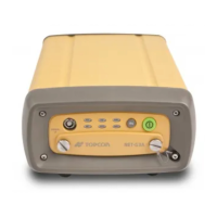
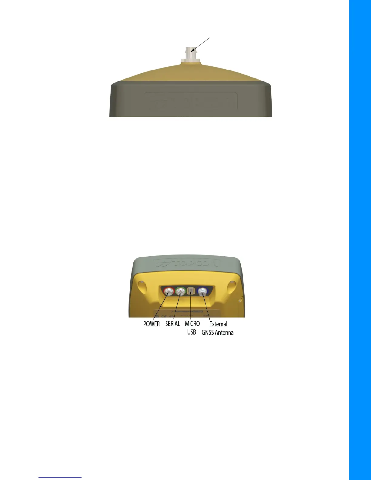
Receiver Enclosure Bottom—Connectors
• Power connector—outlined in red. This connector is used to connect the receiver to an external
power source. This connector can also be used to charge the battery. The body of the connector
on the corresponding cable is red. For additional specification information see
Table 9-6.
• Serial connector—outlined in green. This connector is used for data communication between
the receiver and an external device. For additional specification information see
Table 9-7.
• Micro-USB connector—outlined in yellow. This connector is used for high-speed data transfer
and communication between the receiver and an external device. For additional specification
information see
Table 9-8.
• GNSS Radio Antenna Connector—outlined in blue. The SMB connector that is used to connect
an external GNSS antenna for use in base station and rover station setup.
Figure 2-11: Receiver Enclosure Bottom—Connectors
 Loading...