Measuring Antenna Height
6-5
P/N: 1023998-01
System Setup
– connect the external antenna to the External GNSS Antenna Connector using the External
Antenna Cable (P/N 1006447-01).
• Using TRU:
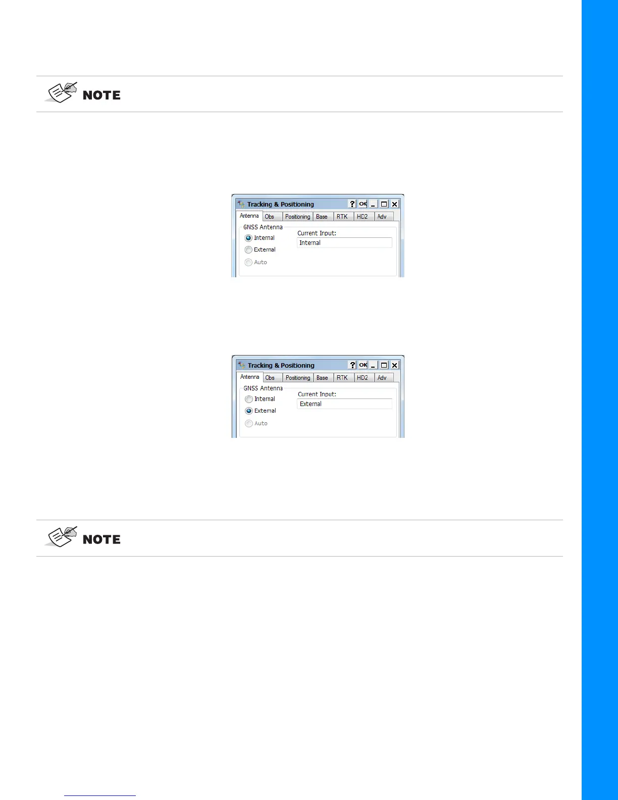
– select Receiver SettingsTracking and Positioning;
– In the Antenna tab, the internal antenna of HiPer VR is set for this receiver by default;
Figure 6-5: Configuration HiPer VR with Internal Antenna in TRU
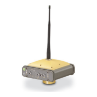
– Select the
External
radio button to activate an external type for HiPer VR receiver. Click OK
button to sent this change to the receiver:
Figure 6-6: Configuration HiPer VR with External Antenna in TRU
– connect the external antenna to the External GNSS Antenna Connector using the External
Antenna Cable (P/N 1006447-01).
When the external antenna is selected, the HiPer VR supplies a voltage in the range from +4.5 V to
+5.5 V to the central pin of the SMB antenna connector. Maximum antenna current equals to 120 mA.
Measuring Antenna Height
The receiver calculates the coordinates of the antenna’s phase center. To determine the coordinates
of the station marker, specify the following:
• measured height of the antenna above the station marker
• method of measuring the antenna height
• model of the antenna/receiver used
After this change the receiver will track GNSS signals only with external antenna.
After this change the receiver will track GNSS signals only with external antenna.