90
4 STANDARD MEASUREMENT MODE
4.5 Data Output
Result of measurement is transferred from the IS series to Data Collector.
[Example: Distance measurement mode]
The following data will be output at each mode.
•
The display and the output at the coarse mode are the same as the contents above.
•
Output at the tracking mode is displayed as distance data only (HD,VD or SD).
1
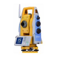
With the SETUP mode, set the communication
parameters.
Refer to Chapter 6 “PARAMETERS SETTING
MODE” .
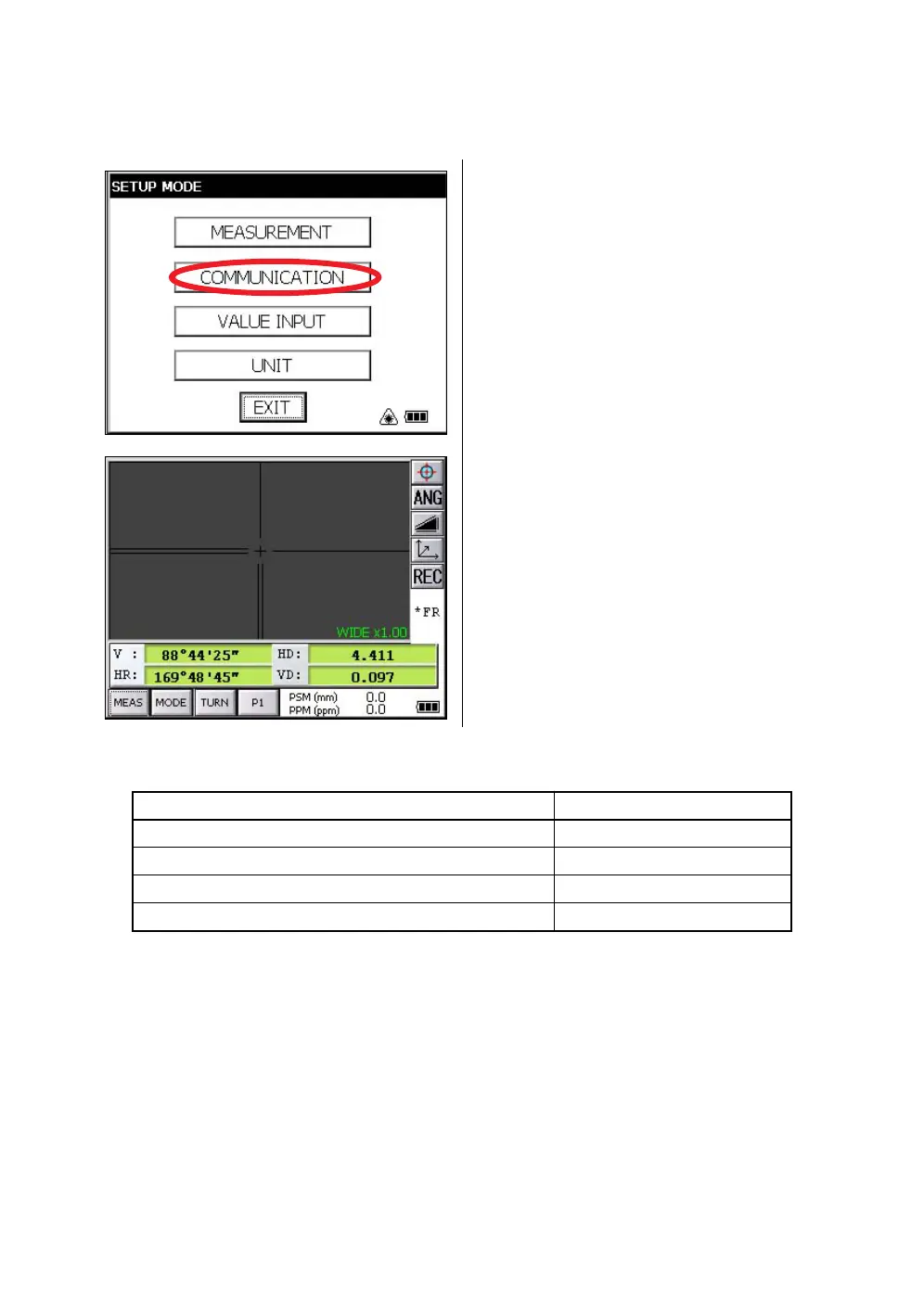
2
After setting the communication parameters,
select the distance measurement mode.
3
Operate the data collector to measure the
distance.
Measurement will be started.
After the measurement, the result will be
shown and transferred to the Data Collector.
Mode Output
Angle mode ( V,HR or HL) ( V in percent) V, HR (or HL)
Horizontal distance mode (V,HR, HD, VD) V, HR, HD, VD
Slope distance mode (V, HR,SD) V, HR, SD,HD
Coordinate mode N, E, Z, HR
 Loading...