50
The radio buttons CA/L1, P/L1 and the checkbox P/L2, which are grouped within
the Measurements Sent area, allow the user to specify which measurement types will be in-
cluded into the corresponding CMR messages broadcasted by the reference station. The radio but-
tons correspond to the receiver parameter /par/cmr/base/pcode. The checkbox P/L2 is associated
with the receiver parameter /par/cmr/base/meas/p2. If the receiver is a single-frequency unit, the con-
trols P/L1 and P/L2 will not be available.
The spin box GLONASS message allows the user to specify which message types will be asso-
ciated with GLONASS measurements. You can choose any unused message types between 3 and 7.
The spin box is associated with the receiver parameter /par/cmr/base/glo/type.
Click the Configuration of Receiver Ports button to go to the Ports tab. For a descrip-
tion of this tab, refer to section 4.2.4.6 of this manual.
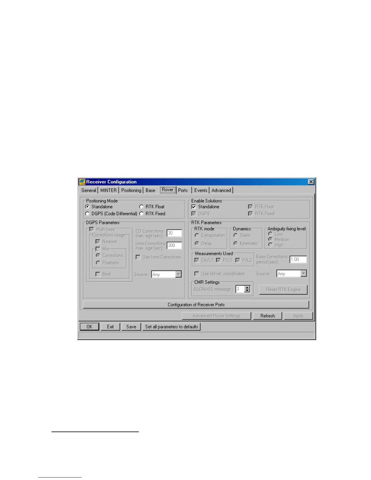
4.2.4.5. Rover
In the tab, one can configure a receiver as a rover station (see Figure 34).
Figure 34. “Rover” tab
The Positioning Mode radio button group permits the user to select one of the four available
positioning modes.
DGPS Parameters
To switch a roving receiver to Multi-base mode, select the Multi-base checkbox. In this mode,
the rover is able to use differential corrections received from more than one reference station
20
.
This checkbox is associated with the receiver parameter /par/pos/cd/mult/mode.
20
Currently, this mode allows the rover to use up to five reference stations simultaneously.