64
The user is able to monitor the offset reduction in the Clock offset field of the GEO tab. After
you select Freq. Locked, one will notice that the value in Clock offset will
have started to reduce and soon (usually in a few minutes) it will become equal to
zero, while in contrast Osc. Offset will not change much.
• The Freq. and Time Locked radio button means that the receiver will adjust
both the internal oscillator’s frequency until the measured frequency offset is reduced
to zero and the internal clock until it gets fully synchronized with the specified refer-
ence time scale.
Switching from Freq. Locked or Freq. and Time Locked to Off may
result in a temporary loss of lock to satellites.
Freq. Locked guarantees that the receiver’s 20 MHz output will have long-
term stability, not necessarily short-term stability. However, there is a way to as-
sure that both of these characteristics will be good enough. It can be done by se-
lecting Enable Co-op tracking on the Loops Management subtab.
The radio buttons are associated with the receiver parameter /par/osc/mode.
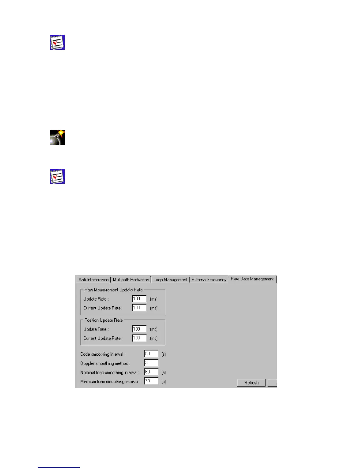
Raw Data Management
This subtab, which is shown in Figure 43, contains the controls for specifying the frequency at
which the receiver will update raw measurement and position. Also, one may set up the controls
that affect the signal processing.
Figure 43. “Raw Data Management” subtab
The Raw Measurement Update Rate group allows the user to determine the raw data
update period. In the Update Rate edit box, enter a value (in milliseconds) to specify the pe-
riod. The box corresponds to the receiver parameter /par/pos/raw/msint. With Current Update