57
4.2.4.7. Events
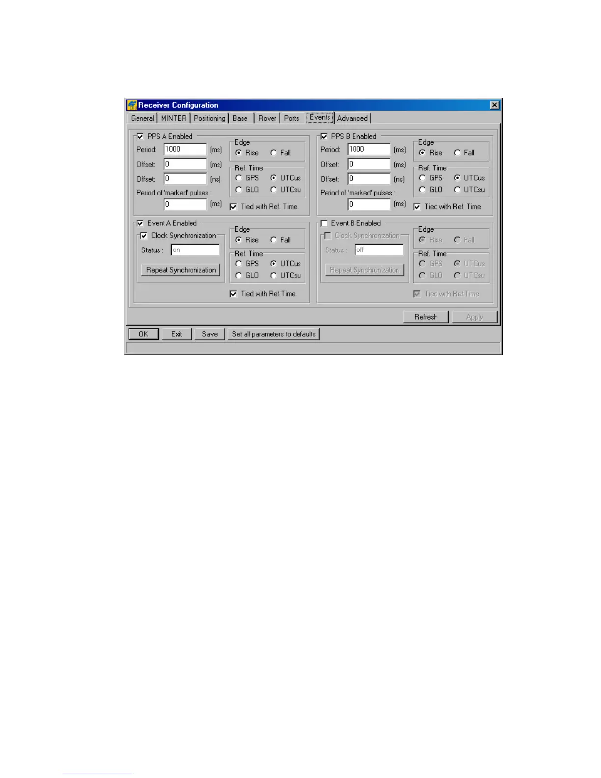
This tab (Figure 38) is used to review and configure the 1PPS signal and Event marker settings.
Figure 38. “Events” tab
The checkboxes PPS A Enabled and PPS B Enabled correspond to the receiver parameters
/par/dev/pps/a/out and /par/dev/pps/b/out, respectively. Selecting these controls, enables the receiver to
generate 1PPS signals and also allows one to modify the settings related to the selected 1PPS sig-
nal.
The Period edit box determines the rate of generating the 1PPS signals via the corresponding
output connector pins. The edit boxes are associated with the receiver parameters
/par/dev/pps/a/per/ms and /par/dev/pps/b/per/ms, respectively.
The user can determine millisecond and nanosecond parts of PPS signal offsets with respect to the
selected reference time grid using the Offset (ms) edit box for millisecond part and Offset
(ns) for nanosecond part. These four edit boxes are associated with the receiver parameters
/par/dev/pps/a/offs/ms, /par/dev/pps/b/offs/ms, /par/dev/pps/a/offs/ns and /par/dev/pps/b/offs/ns, respectively.
With the Period of ‘marked’ pulses edit box, the user specifies the period of the marked
1PPS signal. These edit boxes relate to the receiver parameters /par/dev/pps/a/mper and
/par/dev/pps/b/mper.
Using the Edge radio button group, the user synchronizes the edge (rising or falling) of the 1PPS
signal with the specified reference time. The radio buttons are associated with the receiver parame-
ters /par/dev/pps/a/edge and /par/dev/pps/b/edge.
The Ref. Time radio button group allows the user to select the reference time that the 1PPS sig-
nal will be synchronized with. There are four available reference time scales:
• GPS means GPS system time.