E6582062
6-17 6. [Advanced] How to use parameters
3
4
6
9
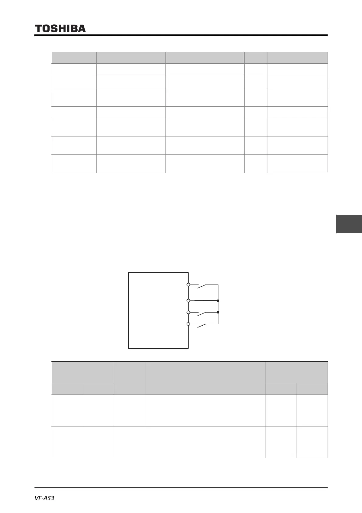
■ Switch terminal setting
V/f1 to V/f4 switching functions are not assigned to the input terminals by default setting. Thus,
assign them to unused input terminals.
Example: When V/f switching 1 function is assigned to the terminal [S1], and V/f switching 2 function
to the terminal [S2].
F176 Manual torque boost 3 0.00-30.00 %
*2
F178 Base frequency 4 15.0 - 590.0 Hz
50.0/60.0
*1
F179 Base frequency voltage 4 240V class: 50-330V
480V class: 50-660V
V
*1
F180 Manual torque boost 4 0.00-30.00 %
*2
F182 Motor overload protection
current 2
Depending on capacity
*2
A
*2 *2
F183 Motor overload protection
current 3
Depending on capacity
*2
A
*2 *2
F184 Motor overload protection
current 4
Depending on capacity
*2
A
*2 *2
*1 Depending on the setup menu. For details, refer to [5. 3. 10], [11. 10].
*2 Depending on capacity. For details, refer to [11. 6].
Input terminal
V/f Parameters selected
Output terminal
(function number)
S1-CC S2-CC No.186 No.188
OFF OFF 1
Base frequency 1: <vL>
Base frequency voltage 1: <vLv>
Manual torque boost 1: <vb>
Motor overload protection current 1: <tHrA>
OFF OFF
ON OFF 2
Base frequency 2: <F170>
Base frequency voltage 2: <F171>
Manual torque boost 2: <F172>
Motor overload protection current 2: <F182>
ON OFF
Title Parameter name Adjustment range Unit Default setting
F
CC
S1
S2
Fwd run
V/f switching 1
V/f switching 2
Sink logic

 Loading...


