E6582062
1. Read first 1-8
1
9
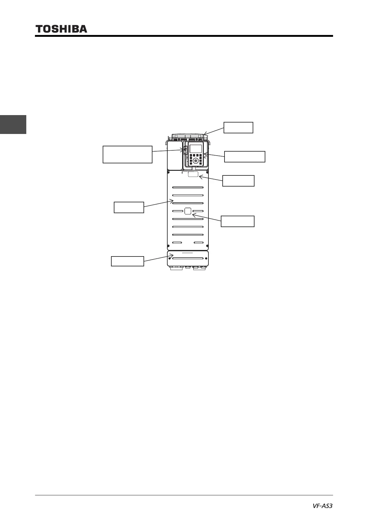
• Top cover
A cover to protect the top of the inverter, which is attached to models with frame size A1 to A5. Remove
this cover to install inverters side by side or in a location with ambient temperature above 50°C for heat
discharge. For how to remove, refer to [2. 2].
■ With frame size A4 or A5
VFAS3-2110P to 2370P, VFAS3-4220PC to 4750PC
• Wiring cover
The models with frame size A4 or A5 have a cover for wiring beneath the front cover. This cover
should be removed to wire to the power terminal block or control terminal block. For how to remove,
refer to [2. 2. 2] (frame size A4) or [2. 2. 3] (frame size A5).
Indicator for
communication
Front cover
[Front]
Operation panel
Top cover
Wiring cover
Danger label
Rating label

 Loading...


