EasyManuals Logo

Toshiba TOSVERT VF-AS3 User Manual

Toshiba TOSVERT VF-AS3
622 pages
To Next Page IconTo Next Page
To Previous Page IconTo Previous Page
Page #48 background imageLoading...
Page #48 background image
E6582062
2. Installation and wiring 2-14
2
9
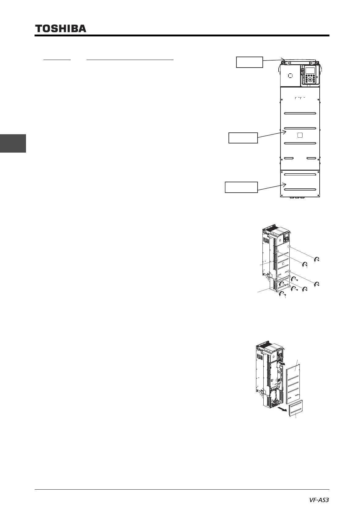
2. 2. 3 With frame size A5
VFAS3-2220P to 2370P, VFAS3-
4450PC to 4750PC
The parts to be removed are as follows.
Front cover in the middle of the front surface (metal)
Wiring cover on the lower side of the front surface
(metal)
Top cover on the top surface (metal)
Each cover can be removed separately.
Front cover
1 Remove four screws of the front cover.
Store the removed screws so as not to be lost.
2 Remove the front cover from the unit.
3 Mount the front cover in the reverse procedure.
Wiring cover
1 Remove four screws of the wiring cover.
Store the removed screws so as not to be lost.
2 Remove the wiring cover from the unit.
3 Mount the wiring cover in the reverse procedure.
Top cover
Front cover
Wiring cover
Front cover
Wiring cover
Screw
Screw
Front cover
Wiring cover

Table of Contents

Other manuals for Toshiba TOSVERT VF-AS3

Questions and Answers:

Question and Answer IconNeed help?

Do you have a question about the Toshiba TOSVERT VF-AS3 and is the answer not in the manual?

Toshiba TOSVERT VF-AS3 Specifications

General IconGeneral
ModelTOSVERT VF-AS3
CategoryInverter
Overload Capacity150% for 60 seconds
Cooling MethodForced Air Cooling
Control MethodV/f control, Sensorless vector control
Braking UnitBuilt-in
Communication ProtocolsModbus RTU, DeviceNet, Profibus DP
Protection FunctionsOvercurrent, Overvoltage, Undervoltage, Overheat, Ground Fault
EnclosureIP20
Operating Temperature-10°C to +50°C
Humidity5-95% (non-condensing)
AltitudeUp to 1000m

Related product manuals