E6582062
6. [Advanced] How to use parameters 6-62
4
4
6
9
Set <F308: Braking resistance> and <F309: Braking resistor capacity> according to the braking
resistor to be connected.
Set the overload time of braking resistor with <F639: Braking resistor overload time>. Set a value so
that a trip occurs at a value 10 times the <F309: Braking resistor capacity> setting. The default
setting is intended for our recommended braking resistors (DGP600 Series excluded). To use the
DGP600 Series, use the characteristic value of overload relay as a guide.
Set the operation level of dynamic braking with <F626: Overvoltage limit operation level>.
To output an overload of braking resistor, allocate the braking resistor overload (OLr) pre-alarm
(function number: "30" , "31") to the output terminal.
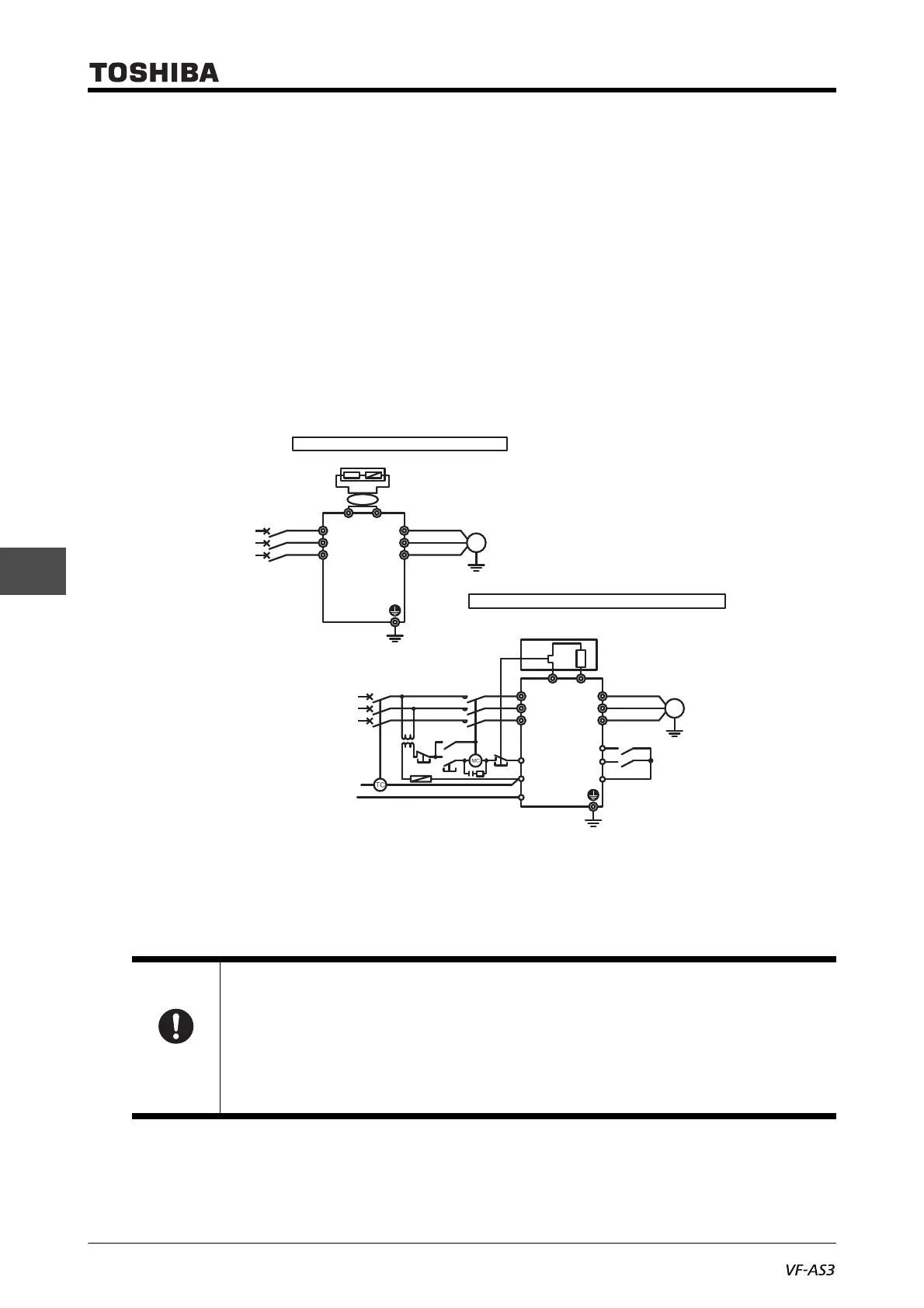
■ Setting example
When using an external braking resistor (option)
The above connection is for the case where MCCB or ELCB with a trip coil is used instead of MC for
TC (trip coil).
Prepare a step-down transformer for the 480V class. It is not required for the 240V class.
For an application that requires the continuous regenerative state, such as moving down of a lifting
gear, press and tension control, or when a deceleration stop is performed for a machine with large
load inertial moment, increase the braking resistor capacity according to the operation rate.
Important
• Be sure to install a thermal relay (THR) to prevent fire.
The inverter is equipped with the functions that protect a braking resistor from overload or
overcurrent. A thermal relay needs to be activated when these protective functions become
disabled.
Select the appropriate thermal relay (THR) according to the braking resistor capacity (watt).
• "Thermal overload relay" is recommended, install it for each motor to be protected.
"Thermal relay with CT" is not available.
In case of external option (with thermal fuse)
In case of thermal relay and external braking resistor
Inverter
Fwd
Rev
Surge absorber
Fuse
Step-down
transformer
MC
TH-R
MCCB
or
ELCB
Three-phase
power supply
Power
supply
U/T1
V/T2
W/T3
R/L1
PBPBe
S/L2
T/L3
FLB
FLC
FLA
F
R
CC
Motor
External braking resistor (option)
PBR
M
Inverter
MCCB
or
ELCB
Power
supply
U/T1
V/T2
W/T3
R/L1
PBPA/
S/L2
T/L3
Motor
External braking resistor (option)
PBR
M

 Loading...


