E6582062
6-147 6. [Advanced] How to use parameters
3
4
6
9
6. 30. 19 Motor PTC thermal protection setting
<F645: Terminal RRPTC trip>
<F646: PTC detection resistance>
<F108: Terminal RR input select>
<F148: Terminal AI4 input select>
<F149: Terminal AI5 input select>
<F637: Terminal AI4 PTC trip>
<F638: Terminal AI5 PTC trip>
■ Function
This function is set to protect the motor from overheating by using PTC, which is integrated in the
monitor.
You can trip the motor. The trip display is "E-32".
■ Parameter setting
■ PTC thermal protection using terminal [RR]
Connect PTC between terminals [RR]-[CC].
Set "4", "5", "7", and "9" with <F108: Terminal RR switching>.
In <F645: Terminal RR PTC trip>, when "0: Disabled" is selected, pre-alarm only, and when "1:
Enabled" is selected, pre-alarm and trip are enabled.
Title Parameter name Adjustment range Unit Default setting
F645 Terminal RR PTC trip 0: Disabled
1: Enabled
0
F646 PTC detection resistance 100 - 9999 Ω 3000
F656 PTC detection
temperature
0 - 200 °C 90
F108 Terminal RR input 1: Voltage input (0-10V)
2, 3: -
4: PTC input
5: PT100 (2-wire) input
6: -
7: PT100 (2-wire) input
8: -
9: KTY84 input
1
F148 Terminal AI4 input select 1: Voltage input (0-10 V)
2: Voltage input (-10 to +10 V)
3: Current input (0-20 mA)
4: PTC input
5: PT100 (2-wire) input
6: PT100 (3-wire) input
7: PT100 (2-wire) input
8: PT1000 (3-wire) input
9: KTY84 input
0
F149 Terminal AI5 input select
F637 Terminal AI4 PTC trip 0: Disabled 0
F638 Terminal AI5 PTC trip 1: Enabled
0.0HzSTOP
14:04
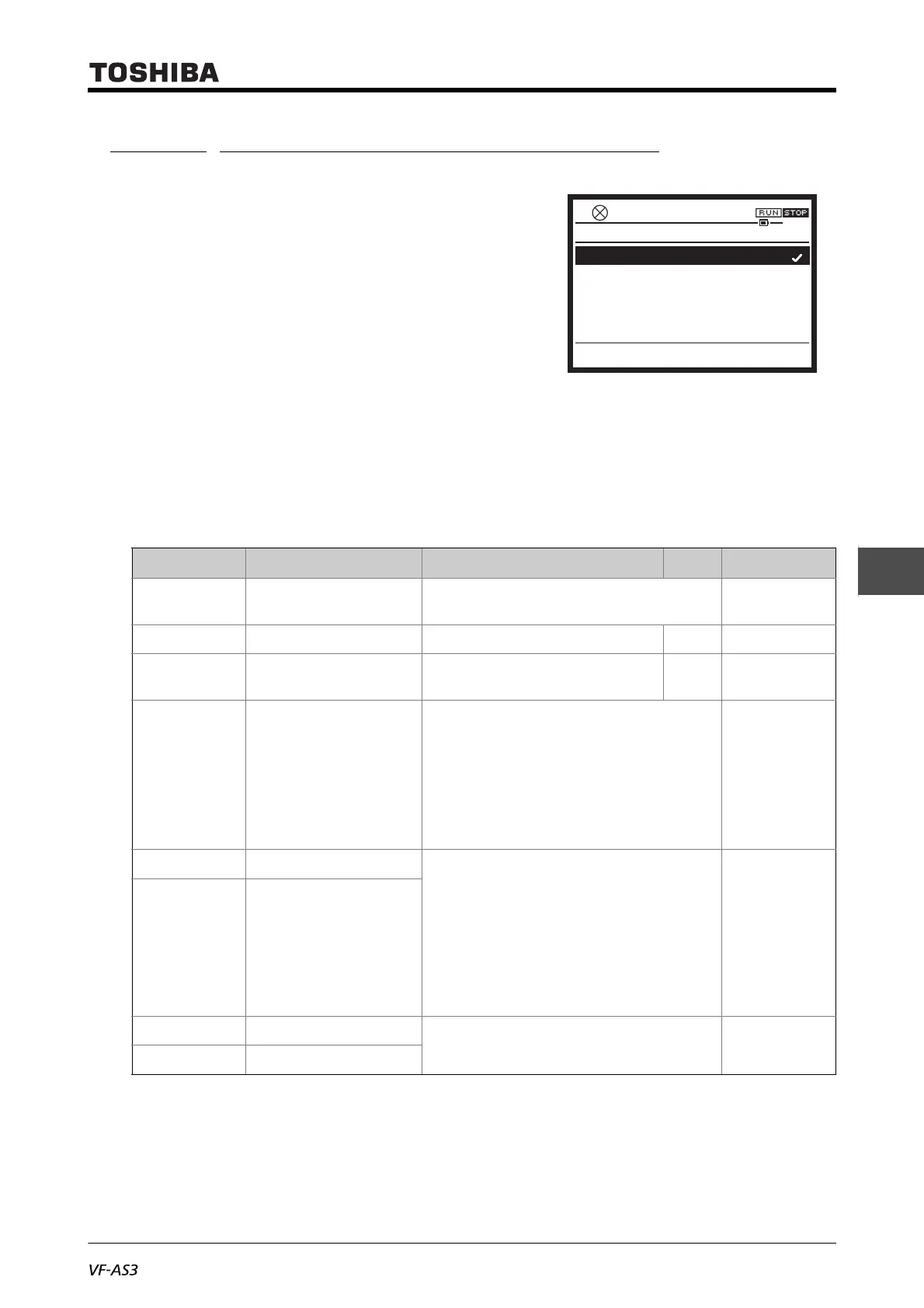
F645 : Terminal RR PTC trip
0: Disabled
1: Enabled

 Loading...


