E6582062
7-11 7. Operating using external signals
3
4
7
9
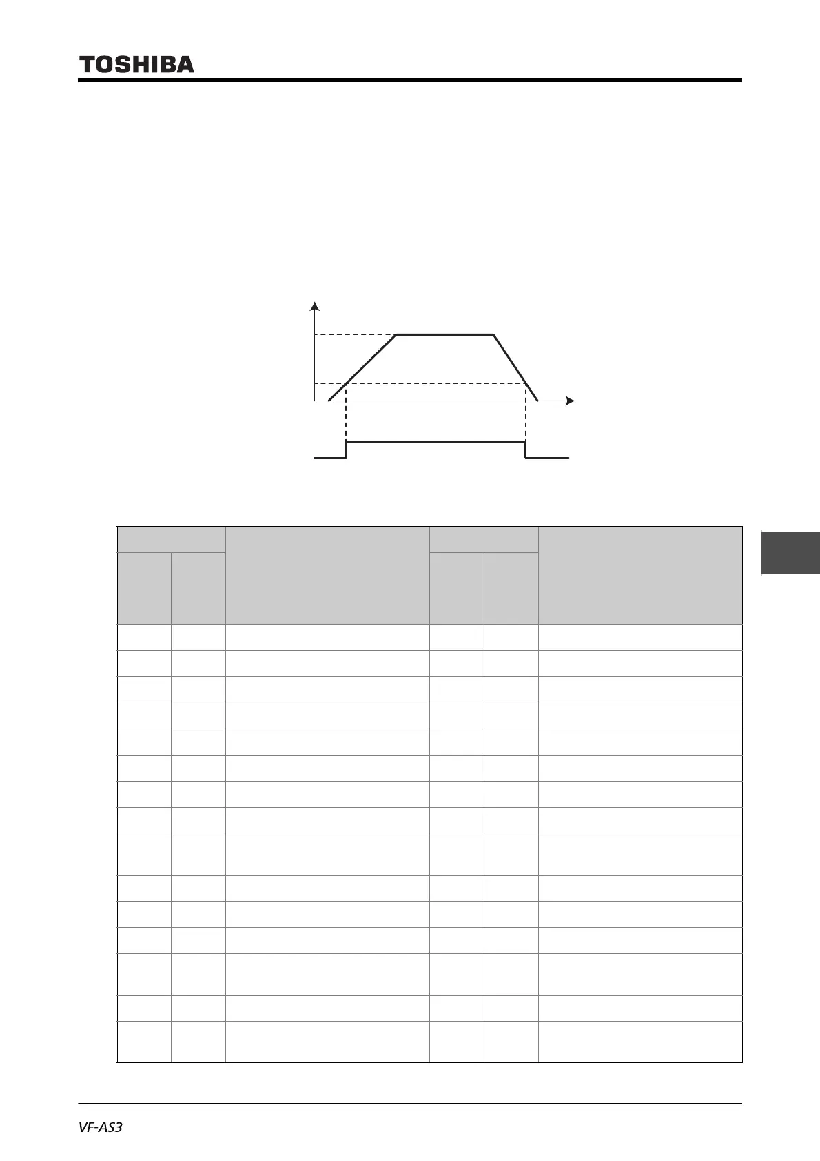
■ Usage example 2: Outputting braking signals
The following shows an example for outputting the excitation/release signals for the electromagnetic
brake.
To output the braking signals from the terminals [R1A]-[R1C], make setting as follows:
• <F133: Terminal R1 function 1> = "4: Low-speed signal" (default setting)
• <F100: Low-speed signal output frequency> = "2.5" (Hz) (setting example)
Set <F100> to the value for the motor rated slip.
■ List of the digital output terminal functions
Setting value
Output terminal function
Setting value
Output terminal function
Positive
logic
Negative
logic
(Inverse)
Positive
logic
Negative
logic
(Inverse)
0 1 Lower limit frequency (LL) 116 117 Failure signal 4
2 3 Upper limit frequency (UL) 118 119 Stop positioning completion
4 5 Low-speed signal 120 121 During sleep
6 7 Acc/Dec completed 122 123 During synchronized Acc/Dec
8 9 Specified frequency attainment 124 125 During traverse operation
10 11 Failure signal 1 126 127 During traverse Dec
12 13 Failure signal 2 128 129 Parts replacement alarm
14 15 Overcurrent (OC) pre-alarm 130 131 Overtorque (OT) pre-alarm
16 17 Inverter overload (OL1) pre-alarm 132 133 Frequency command 1/
Frequency command 2
18 19 Motor overload (OL2) pre-alarm 134 135 Failure signal 3
20 21 Overheat (OH) pre-alarm 136 137 Hand/Auto
22 23 Overvoltage (OP) pre-alarm 138 139 During forced run
24 25 Main circuit undervoltage (MOFF)
alarm
140 141 During fire speed run
26 27 Undercurrent (UC) alarm 142 143 Undertorque alarm
28 29 Overtorque (OT) alarm 144 145 PID1, 2 frequency command
agreement
ON
OFF
Output frequency (Hz)
Time (s)
Frequency command value
<F100: Low-speed signal
output frequency>
[R1A]-[R1C] output
(Low-speed signal)
0

 Loading...


