E6582062
8. Monitoring operation status 8-4
4
4
8
9
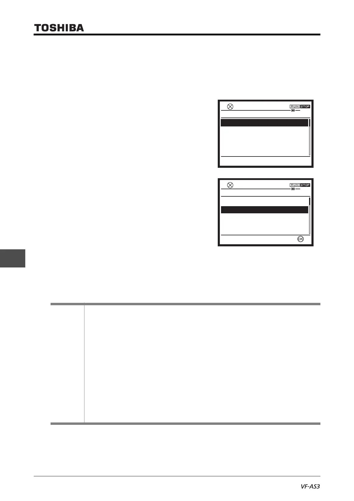
■ Screen configuration of [Monitor mode]
If an "OK" mark is displayed on the [F4] key when you select any of the displayed items, a details
monitor is available. When you press the [F4] key or [OK] key, you can go to the details monitor.
When you press the [i] key, you can check the inverter rating and the CPU version.
1) Direction of rotation
"Forward" or "Reverse" is displayed.
The direction of rotation of the monitor output by
the inverter is displayed whether the motor is run or
stopped.
2) Selected monitor 1 to 8
The monitor items selected with <F711: Monitor
mode 1 display> to <F718: Monitor mode 8 dis-
play> are displayed. In the default setting, the fol-
lowing monitor items are displayed.
• Output current
• Input voltage (DC detection)
• Output voltage
• Torque
• Input power
• Output power
• Inverter load factor
• Motor load factor
Memo
• Output current: The current monitored is displayed in percentage. The value indicated on the
nameplate is 100%. The unit can be switched to A (amperes). Set <F701: Current, voltage
units select> to "1: A (ampere), V (volt)."
• Input voltage: The reference values (100% values) are 200 V (240 V class) and 400 V (480 V
class). The voltage displayed is the voltage determined by converting the voltage measured in
the DC section into an AC voltage. The unit can be switched to V (volts). Set <F701: Current,
voltage units select> to "1: A (ampere), V (volt)."
• Output voltage: The reference values (100% values) are 200 V (240 V class) and 400 V (480 V
class). The voltage displayed is the output command voltage. The unit can be switched to V
(volts). Set <F701: Current, voltage units select> to "1: A (ampere), V (volt)."
• Load factor of inverter: Depending on <F300: Carrier frequency> setting and so on, the actual
rated current may become smaller than the rated output current indicated on the nameplate.
With the actual rated current at that time (after reduction) as 100%, the proportion of the load
current to the rated current is indicated in percent. The load factor is also used to calculate the
conditions for overload trip "OL1".
Direction of rotation
Output current
DC bus voltage
Output voltage
Torque
Top Easy Setting
0.0HzSTOP
12:42
Forward
0%
119%
0%
0%
Monitor Mode
Direction of rotation
Output current
DC bus voltage
Output voltage
Torque
Top Easy Setting
0.0HzSTOP
12:43
Forward
0%
119%
0%
0%
Monitor Mode

 Loading...


