E6582062
2-21 2. Installation and wiring
2
3
9
10
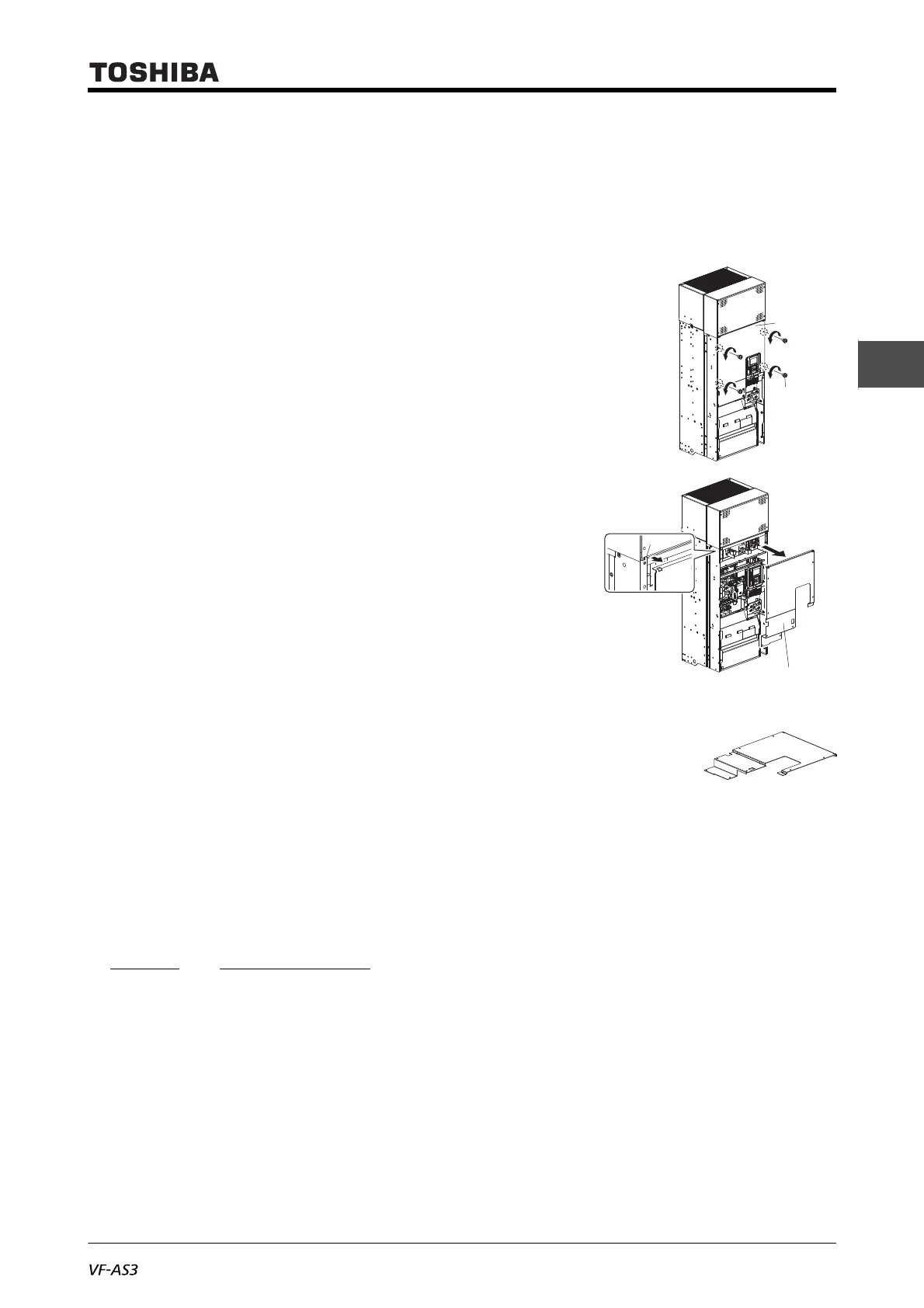
■ Front cover (upper)
1 Remove the front cover (lower) and the DC reactor
cover.
Refer to the procedure above.
2 Remove eight screws of the front cover (upper).
Store the removed screws so as not to be lost.
3 Lift the lower end of the front cover (upper) slightly,
move the front cover (upper) slightly upward and
unfasten two tabs of the unit.
The upper end of the front cover (upper) is caught in
two tabs of the unit.
4 Lift the front cover (upper) and remove it from the unit.
5 Mount the front cover (upper) in the reverse procedure.
First, fit the upper end of the front cover (upper) in two tabs of the unit.
Be sure to mount the front cover (upper) before the front cover (lower) and the DC reactor
cover.
2. 2. 6 Charge lamp
While the charge lamp is on (red), voltage is applied, or high voltage remains in the inverter.
The location of the charge lamp varies depending on the type.
■ With frame size A1 to A5
VFAS3-2004P to 2370P, VFAS3-4004PC to 4750PC
The charge lamp is inside the front cover.
In the case of frame size A1, check the charge lamp in the following procedure. Also for other mod-
els, remove the front cover by referring to [2. 2] and check the charge lamp.
Front cover
(upper)
Screw

 Loading...


