E6582062
2. Installation and wiring 2-56
2
9
FM Output
Multifunction programmable
analog output. 0 - 10 Vdc output
with default setting. With <F681:
Terminal FM switching>, meter
option (0 - 1 mA), current (0 - 20
mA) output, and voltage (0 - 10 V)
output can be switched.
0 - 10 Vdc
(allowable load
resistance: 1 kΩ or
more)
4 - 20 mAdc
(0 - 20 mAdc)
(allowable load
resistance:
500 Ω or less)
AM Output
Multifunction programmable
analog output. 0 - 20 mAdc output
with default setting. With <F686:
Terminal AM switching>, meter
option (0 - 1 mA), current (0 - 20
mA) output, and voltage (0 - 10 V)
output can be switched.
PLC
Output
When the slide switch [SW1] is set
to the sink side or source side, it
can be used as 24 Vdc power
output.
24 Vdc-200 mA
(200 mA in total
with P24)
Compliant with
IEC61131-2
Input
When the slide switch [SW1] is set
to the PLC side, it can be used as
a common terminal for digital input
terminal.
-
P24 Output 24 Vdc power output.
24 Vdc-200 mA
(200 mA in total
with PLC)
Compliant with
IEC61131-2
+SU Input
DC power input to operate the
control circuit. Connect a control
power supply option or 24 Vdc
power supply between [+SU] and
[CC].
24 Vdc- current 1A
or more
STOA Input
STO function that complies with
the safety standard IEC61800-5-2
(this is different function from
programmable digital input).
Function is deactivated by shorting
the terminals [STOA]-[STOB]-[PLC]
with a bridge at factory.
STOA and STOB should be set in
same level. (both HIGH, or both
LOW)
When STOA/STOB are OFF
during motor is running, motor
becomes coast stop. Under this
condition, even if STOA/STOB are
ON, motor is not running unless
run command is once OFF and On
again.
For details, refer to Safety function
manual (E6582067).
Compliant with
IEC61131-2 logic
type 1
• Activate < 5 V,
11 V <
Deactivate
Refer to Safety
Function Manual.
STOB Input
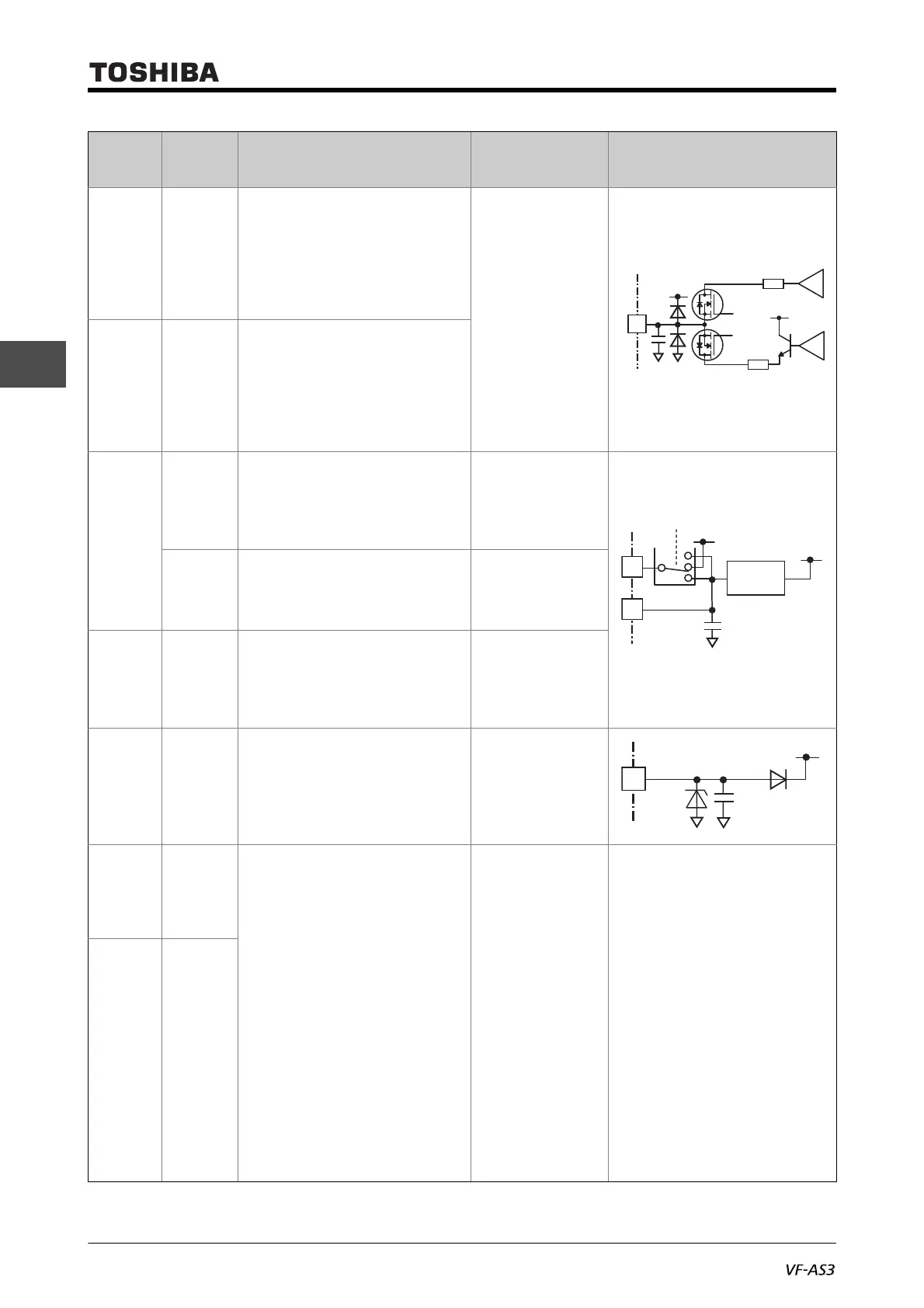
Terminal
symbol
Input/
output
Function
Electrical
specifications
Internal circuit
+24V
68
137
0~20mA
+
–
0~10V
+
–
+24V
FM
AM
+24V
Current
limiter
P24
PLC
4
EXT
SW1

 Loading...


