E6581158
E-28
5
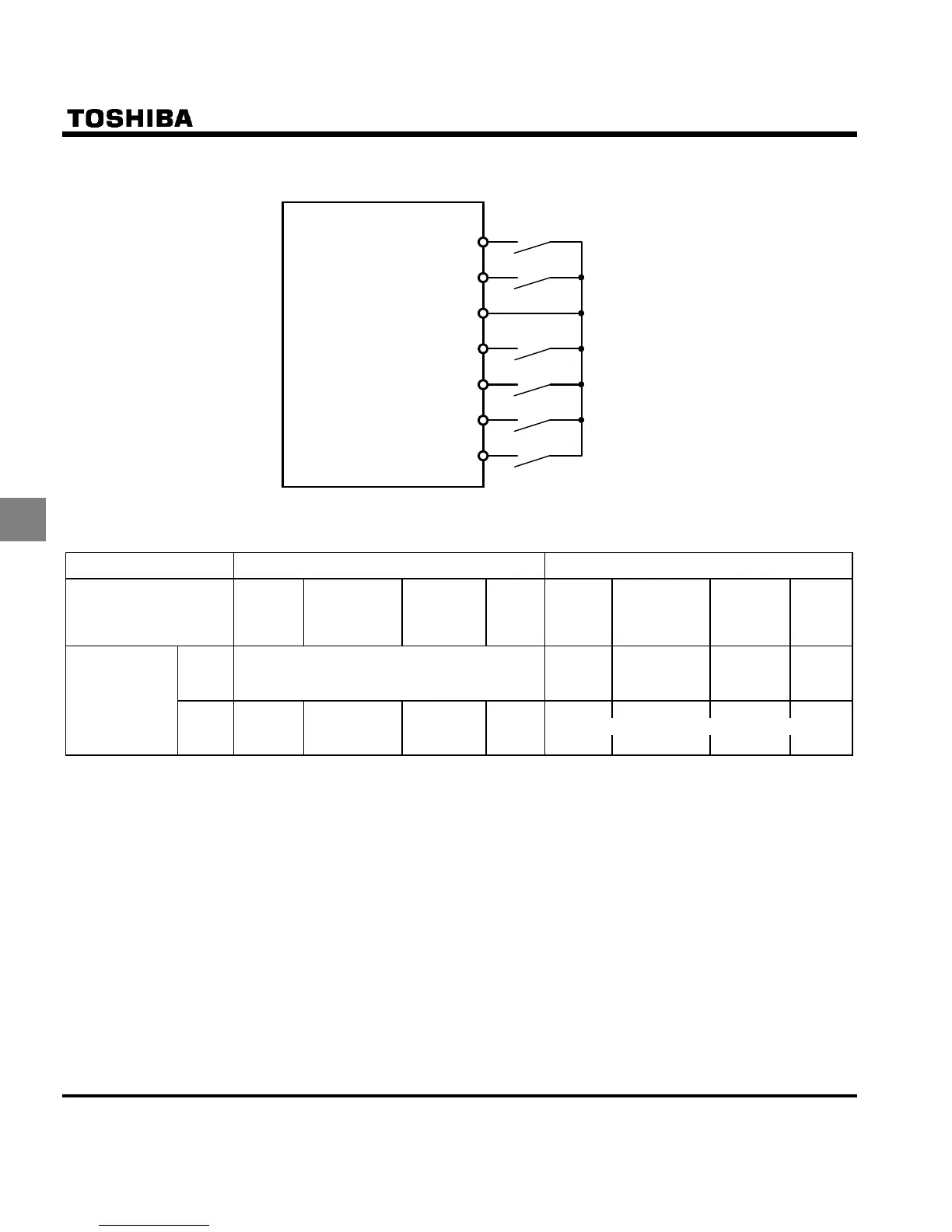
[Example of a connection diagram] (SW1 set to sink logic)
F (Forward run)
CC
RES
S2
S3
S1
R (Reverse run)
Forward
Reverse
Preset-speed 1 (SS1)
Preset-speed 3 (SS3)
Preset-speed 4 (SS4)
Preset-speed 2 (SS2)
Common
3) Using other speed commands with preset-speed command
Command mode selection
EOQF
0: Terminal board 1: Operation panel
Frequency setting
mode selection HOQF
0: Built-in
potentio
meter
1: VIA
2: VIB
5: UP/DOWN
or
6: VIA + VIB
3: Operation
panel
4:Comm
unicati
on
0: Built-in
potentio
meter
1: VIA
2: VIB
5: UP/DOWN
or
6: VIA + VIB
3: Operation
panel
4:Commu
nication
Entered Preset-speed command valid Note)
Potenti-
ometer
command
valid
Terminal com-
mand valid
Operation
panel com-
mand valid
Communic
ation
command
valid
Preset-speed
command
Not
entered
Potenti-
ometer
command
valid
Terminal com-
mand valid
Operation
panel com-
mand valid
Communi
cation
command
valid
Note) The preset-speed command is always given priority when other speed commands are input at the
same time.
Below is an example of 7-step speed operation with standard default setting.
(The inverter doesn't accept Preset-speed command.)

 Loading...


