E6581158
F-83
6
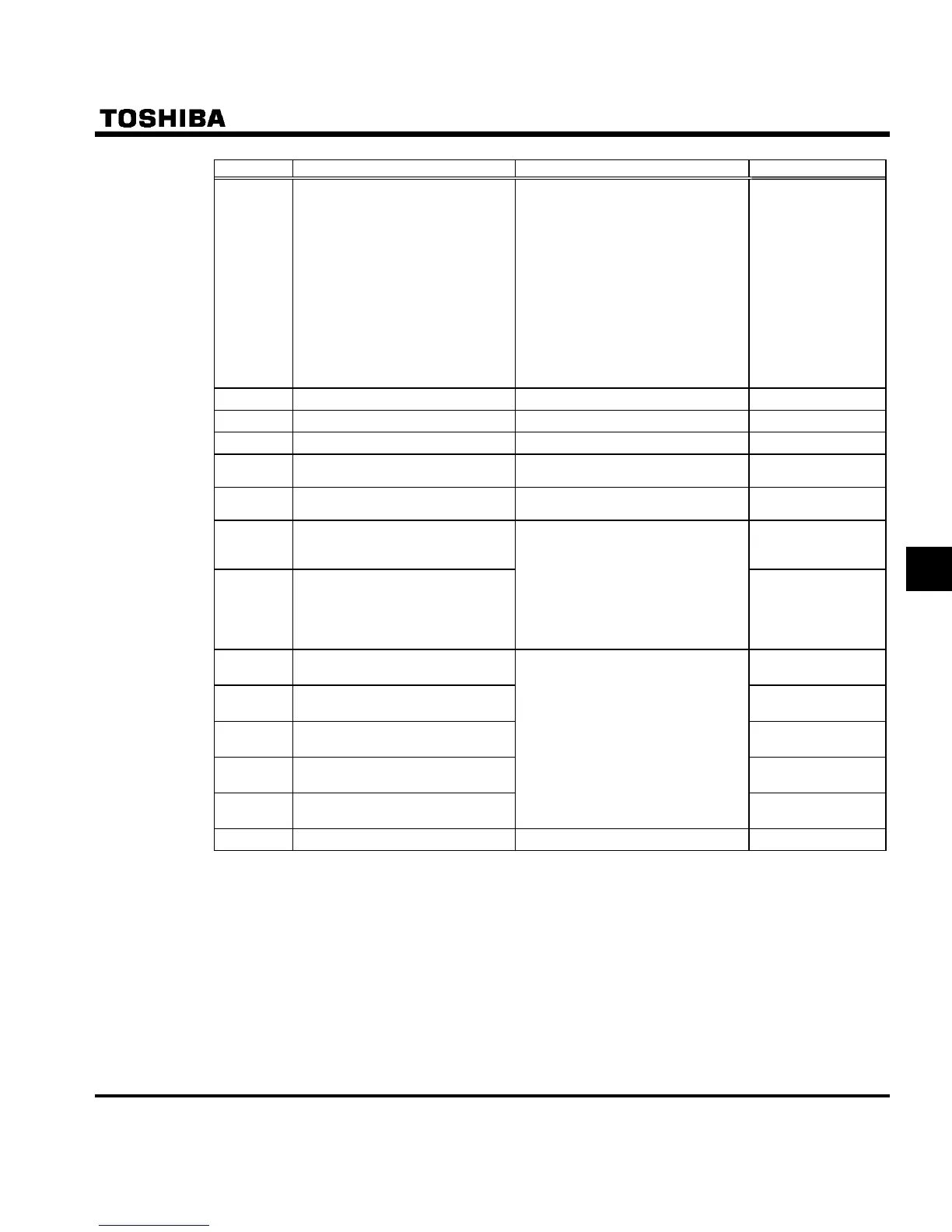
Title Function Adjustment range Default setting
H
Setting of master and slave
inverters
for communications between
inverters
0: Slave inverter (0 Hz command
issued in case the master
inverter fails)
1: Slave inverter (Operation con-
tinued in case the master
inverter fails)
2: Slave inverter (Emergency stop
tripping in case the master
inverter fails)
3: Master inverter (transmission of
frequency commands)
4: Master inverter (transmission of
output frequency signals)
0
H Point # 1 setting 0-100 (%) 0
H Point # 1 frequency 0-500.0 (Hz) 0.0
H Point # 2 setting 0-100 (%) 100
H
Point # 2 frequency 0-500.0 (Hz)
50.0 (WP type)
60.0 (WN, AN type)
H
Selection of communication
protocol
0: Toshiba inverter protocol
1: ModbusRTU protocol
0
H Block write data 1 0
H Block write data 2
0: No selection
1: Command 1
2: Command 2
3: Frequency command
4: Output data on the terminal
board
5: Analog output for communica-
tions
0
H Block read data 1 0
H Block read data 2 0
H Block read data 3 0
H
Block read data 4 0
H
Block read data 5
0: No selection
1: Status information
2: Output frequency
3: Output current
4: Output voltage
5: Alarm information
6: PID feedback value
7: Input terminal board monitor
8: Output terminal board monitor
9: VIA terminal board monitor
10: VIB terminal board monitor
0
H
Free notes 0-65535 0
* Disabled ........... Indicates that the inverter will not be tripped even if a communication error occurs.
Trip ...................The inverter trips when a communication time-over occurs.
In this case a trip information GTT flashes on and off on the operation panel.

 Loading...


