E6581158
H-3
8
(Continued)
Item displayed
Key
operated
LED
display
Communi-
cation No.
Description
Past trip 4
PGTT ⇔
FE13 Past trip 4 (displayed alternately)
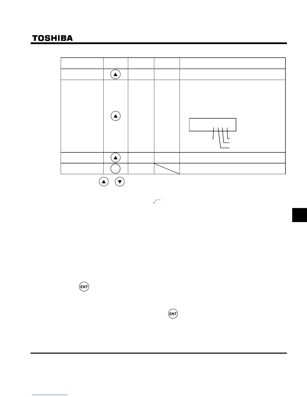
Life alarm
information
O ___K
FE79
The ON/OFF status of each of the cooling fan, cir-
cuit board capacitor, main circuit capacitor or life
alarm of cumulative operation time is displayed in
bits.
ON:
OFF: _
Cumulative
operation time
V FE14
The cumulative operation time is displayed.
(0.01=1 hour, 1.00=100 hours)
Default display
mode
The operation frequency is displayed (Operation at
60Hz).
Note 1: Press the or key to change items displayed in the status monitor mode.
Note 2: You can switch between % and A (ampere)/V (volt), using the parameter H (current/voltage unit
selection).
Note 3: The input (DC) voltage displayed is 1
2
times as large as the rectified d.c. input voltage.
Note 4: The number of bars displayed varies depending on the setting of H (analog input/logic input func-
tion selection). The bar representing VIA or VIB is displayed only when the logic input function is as-
signed to the VIA or VIB terminal, respectively.
If H = : Neither the bar representing VIA nor the bar representing VIB is displayed.
If H = or : The bar representing VIA is not displayed.
The bar representing VIB is displayed.
If H = or : Both the bar representing VIA and VIB are displayed.
Note 5: The number of bars displayed varies depending on the setting of H (logic output/pulse train output
selection). The bar representing the OUT-NO terminal is displayed only when logic output function is as-
signed to it.
If H = : The bar representing OUT-NO is displayed.
If H = : The bar representing OUT-NO is not displayed.
Note 6: The integrated amounts of input and output power will be reset to zero, if you press and hold down the
key for 3 seconds or more when power is off or when the input terminal function CKWH (input
terminal function: 51) is turned on or displayed.
Note 7: Past rip records are displayed in the following sequence: 1 (latest trip record) ⇔2⇔3⇔4 (oldest trip rec-
ord). If no trip occurred in the past, the message “PGTT” will be displayed. Details on past trip record
1, 2, 3 or 4 can be displayed by pressing the key when past trip 1, 2, 3 or 4 is displayed. For more
information, see 8.1.2.
Note 8: The life alarm is displayed based on the value calculated from the annual average ambient temperature,
operation time and load current specified using H. Use this alarm as a guide only, since it is based
on a rough estimation.
Note 9: The cumulative operation time increments only when the machine is in operation.
MO
MOMO
MODE
DEDE
DE
Note 7
Note 8
Note 9
O ___K
Cooling
fan
Cumulative
operationtime
Control circuit board capacitor
Main
circuit
capacitor

 Loading...


