E6581158
I-4
9
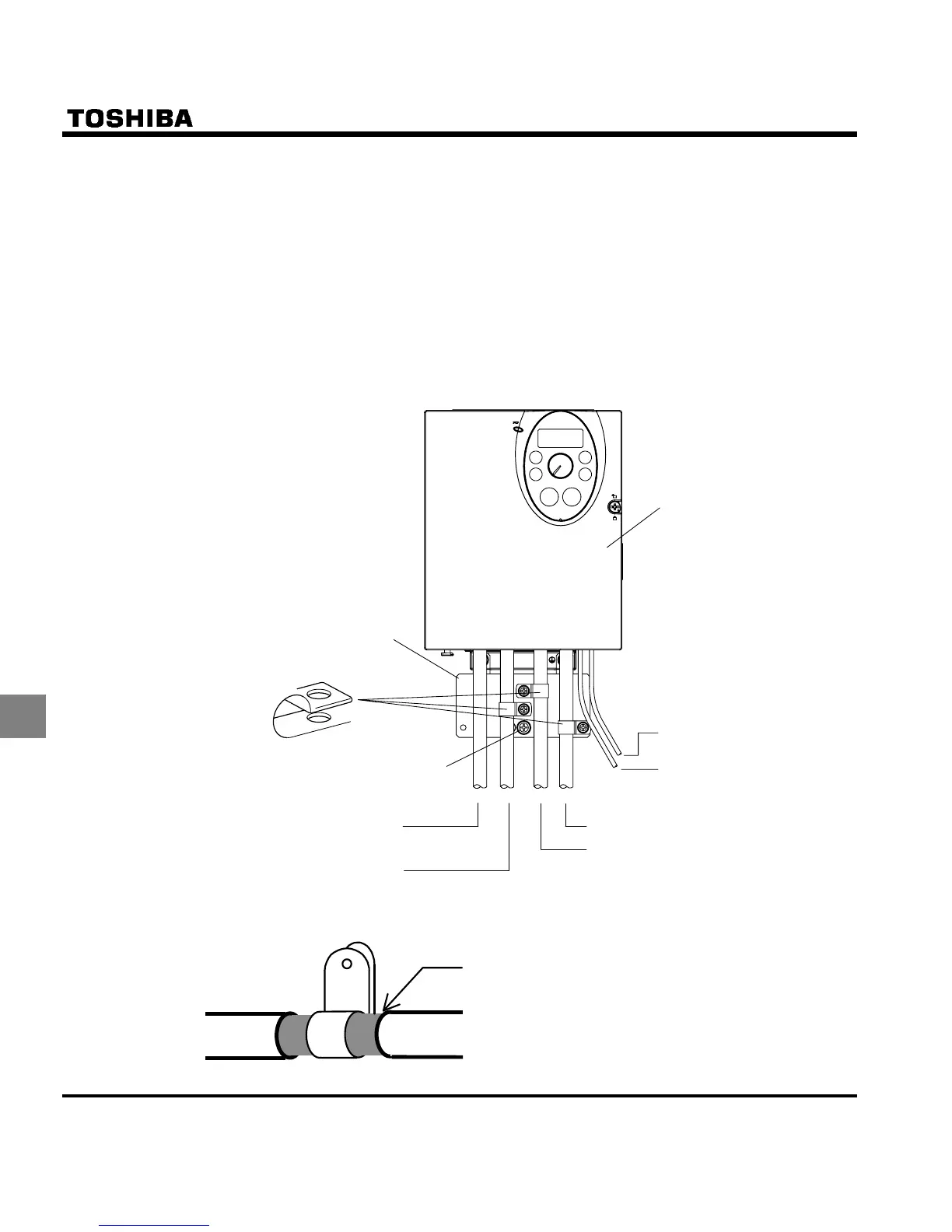
(3) Install the inverter and the filter on the same metal plate. It is more effective in limiting the radiation noise to
install the inverter in a sealed steel cabinet. Using wires as thick and short as possible, earth the metal plate
and the control panel securely with a distance kept between the earth cable and the power cable.
(4) Route the EMI filter input and output wires apart from each other.
(5) To suppress radiation noise from cables, ground all shielded cables through a noise cut plate.
It is effective to earth shielded cables in the vicinity of the inverter, cabinet and filter (within a radius of 10cm
from each of them). Inserting a ferrite core in a shielded cable is even more effective in limiting the radiation
noise.
(6) To further limit the radiation noise, insert a zero-phase reactor in the inverter output line and insert ferrite
cores in the earth cables of the metal plate and cabinet.
[Example of wiring]
Control wiring (Shielded cables)
Motor wiring (Shielded cables)
Braking resistor wiring (Shielded cables)
Power supply wiring
FL relay wiring
VF-S11
To relay
Grounding terminal screw
(Note 1)
EMC plate
Note 1: Strip and earth the shielded cable, following the example shown in Fig.
Strip the cable and fix it to the metal plate by
means of a metal saddle for electrical work or
equivalent.
Shielded cable

 Loading...


