*) See Table 92 Digital output signals (Control keypad: Menu M2 -> G2.3.1).
**) See Table 94 Analogue output 1 (Control keypad: Menu M2 -> G2.3.3), Table 95 Analogue
output 2 (Control keypad: Menu M2 -> G2.3.4) and Table 96 Analogue output 3 (Control keypad:
Menu M2 -> G2.3.7).
NOTE!
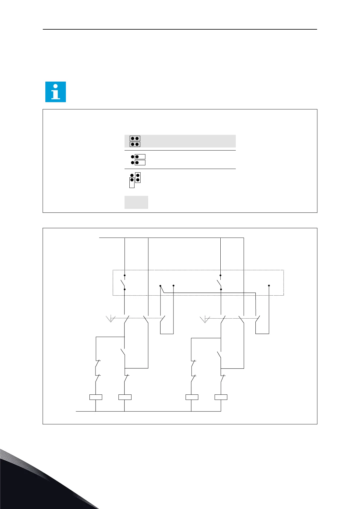
See jumper selections below. More information in the product's User Manual.
Jumper block X3:
CMA and CMB grounding
CMB connected to GND
CMA connected to GND
CMB isolated from GND
CMA isolated from GND
CMB and CMA internally
connected together,isolated
from GND
= Factory default
Fig. 20: Jumper selections
22
23
12
9
Autom. Mains
25
26
230 VAC
S1
K1 K1.1
K1.1
K2
K2
K1
VACON OPT-A2
K1
K2
K2 K2.1
M1/Vacon M2/mainsM1/mains
24 VDC
S2
K2.1
K1
10
RO1
RO2
DIN2
DIN3
Autom.
OO
Mains
M2/Vacon
Fig. 21: Pump autochange system, principal control diagram
VACON · 198 PUMP AND FAN CONTROL APPLICATION
7
TEL. +358 (0)201 2121 · FAX +358 (0)201 212 205
 Loading...


