EasyManuals Logo

Vacon NX series Applications Manual

Vacon NX series
392 pages
To Next Page IconTo Next Page
To Previous Page IconTo Previous Page
Page #216 background imageLoading...
Page #216 background image
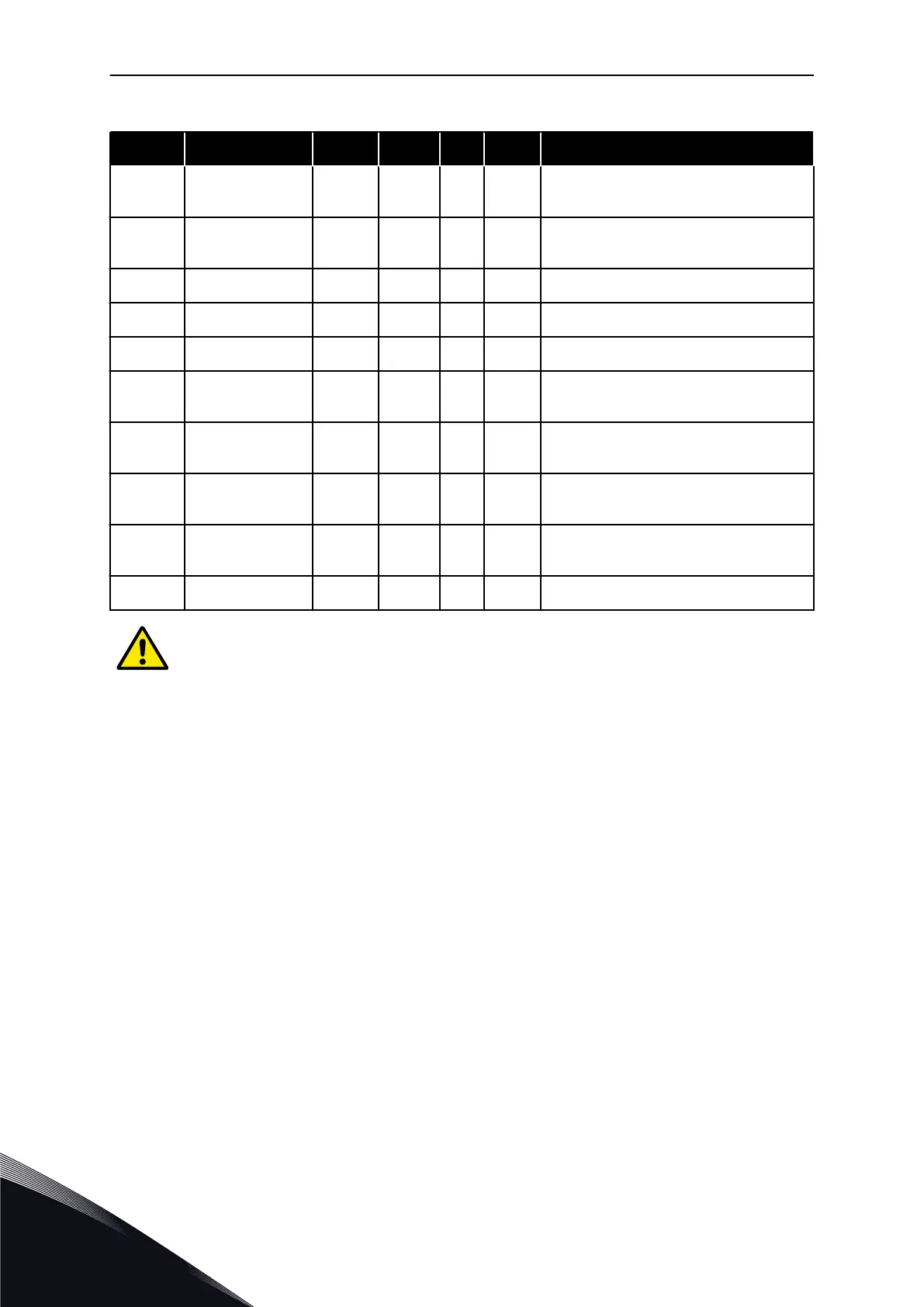
Table 92: Digital output signals (Control keypad: Menu M2 -> G2.3.1)
Index Parameter Min Default Cust ID Description
P2.3.1.22
Analogue input
supervision limit
0.1 0.1 463
P2.3.1.23
Motor regulator
activation
0.1 0.1 454
A limit controller is active
P2.3.1.24 Fieldbus DIN 1 0.1 0.1 455
P2.3.1.25 Fieldbus DIN 2 0.1 0.1 456
P2.3.1.26 Fieldbus DIN 3 0.1 0.1 457
P2.3.1.27
Autochange 1/Aux
1 control
0.1 B.1 458
P2.3.1.28
Autochange 2/Aux
2 control
0.1 B.2 459
P2.3.1.29
Autochange 3/Aux
3 control
0.1 0.1 460
P2.3.1.30
Autochange 4/Aux
4 control
0.1 0.1 461
P2.3.1.31 Autochange 5 0.1 0.1 462
CAUTION!
Be ABSOLUTELY sure not to connect two functions to one and same output in order
to avoid function overruns and to ensure flawless operation.
VACON · 216 PUMP AND FAN CONTROL APPLICATION
7
TEL. +358 (0)201 2121 · FAX +358 (0)201 212 205

Table of Contents

Other manuals for Vacon NX series

Questions and Answers:

Question and Answer IconNeed help?

Do you have a question about the Vacon NX series and is the answer not in the manual?

Vacon NX series Specifications

General IconGeneral
Product typeAC Drive
Output voltage range0-Uin
Frequency range0-500 Hz
Enclosure classesIP00, IP21
Mounting typesWall
Braking chopperIntegrated or external
EMC filterBuilt-in or external
Control modesScalar, Vector
Protection featuresOvercurrent, overvoltage, undervoltage, overtemperature, short circuit
Communication optionsModbus, Profibus, CANopen, Ethernet
Ambient temperature range-10°C to +50°C
Cooling methodAir-cooled

Related product manuals