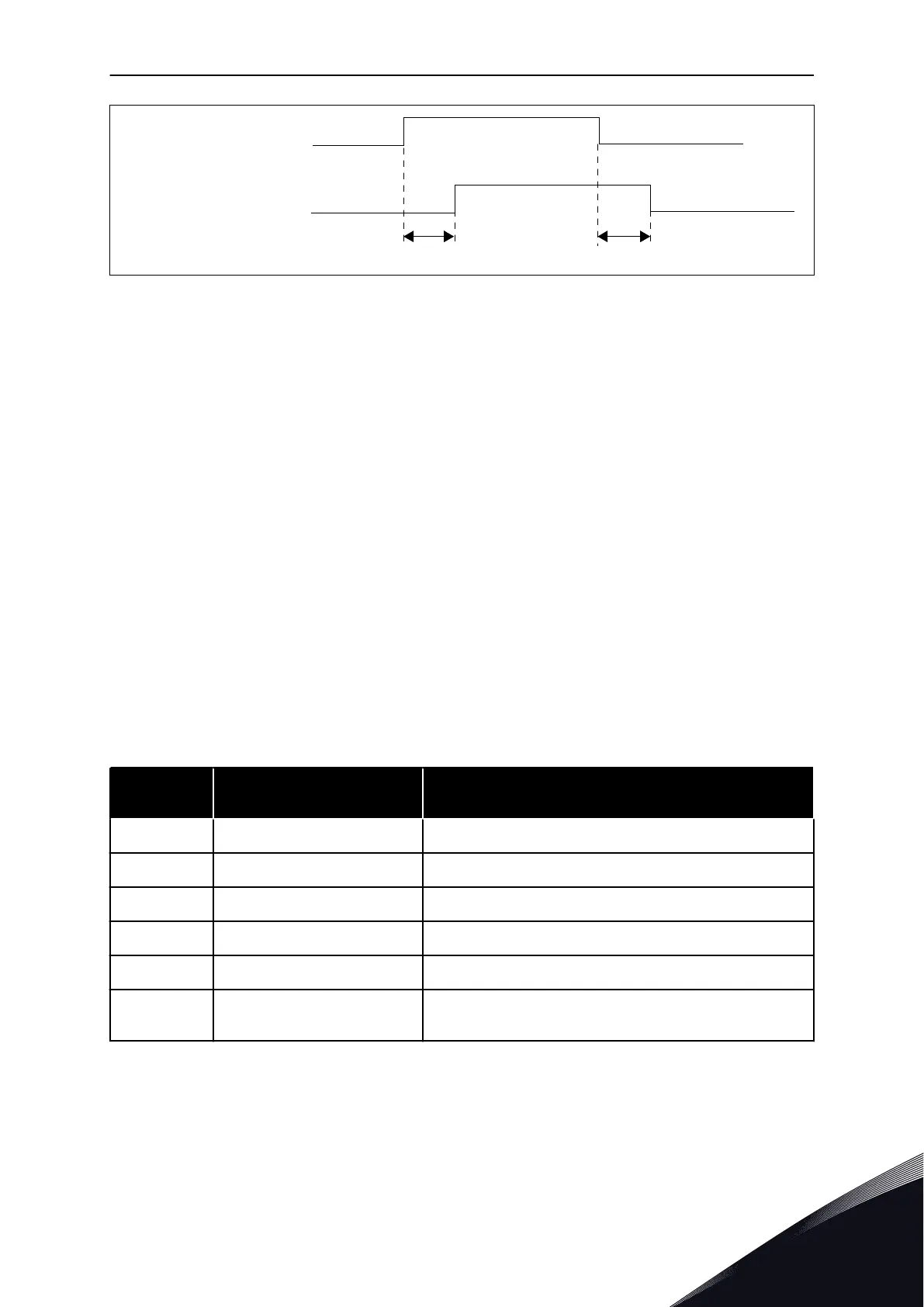
ON-delay OFF-delay
DO1 or DO2 output
Signal programmed to
digital output
Fig. 65: Digital outputs 1 and 2, on- and off-delays
489 DIGITAL OUTPUT 2 SIGNAL SELECTION * 6 (2.3.2.1)
See ID486.
490 DIGITAL OUTPUT 2 FUNCTION 6 (2.3.2.2)
See ID312.
491 DIGITAL OUTPUT 2 ON-DELAY 6 (2.3.2.3)
492 DIGITAL OUTPUT 2 OFF-DELAY 6 (2.3.2.4)
With these parameters you can set on and off delays for the digital outputs.
See parameters ID487 and ID488.
493 ADJUST INPUT 6 (2.2.1.4)
With this parameter you can select the signal, according to which the frequency reference to
the motor is fine adjusted.
Table 149: Selections for parameter ID493
Selection
number
Selection name Description
0 Not used
1 Analogue input 1
2 Analogue input 2
3 Analogue input 3
4 Analogue input 4
5
Signal from fieldbus (FBPro-
cessDataIN)
See Chapter 8.7 Fieldbus control parameters (IDs 850 to 859)
and parameter group G2.9
PARAMETER DESCRIPTIONS VACON · 299
24-HOUR SUPPORT +358 (0)201 212 575 · EMAIL: VACON@VACON.COM
8
 Loading...


