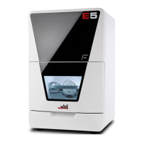
4.3 Connection panel
1. 2x USB port 2.0 type A (for future extensions)
2. 1x USB port 2.0 type B (for future extensions)
3. Network port (Ethernet RJ-45)
Connecting the CAM computer (
page 17)
4. Power connection including glass fuse T6,3A L250V
Establishing the electric connection (
page 20)
Exchanging the main fuse (
page 94)
5. Main power switch
Commissioning (
page 21)
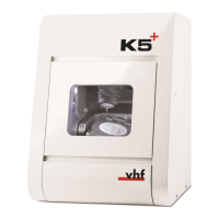
4.4 Start button
FIG. 2
The Start button is used to start and interrupt a job.
To press the Start button, place a finger on it.
Starting jobs (page 37)
Interrupt and continue machining (page 37)
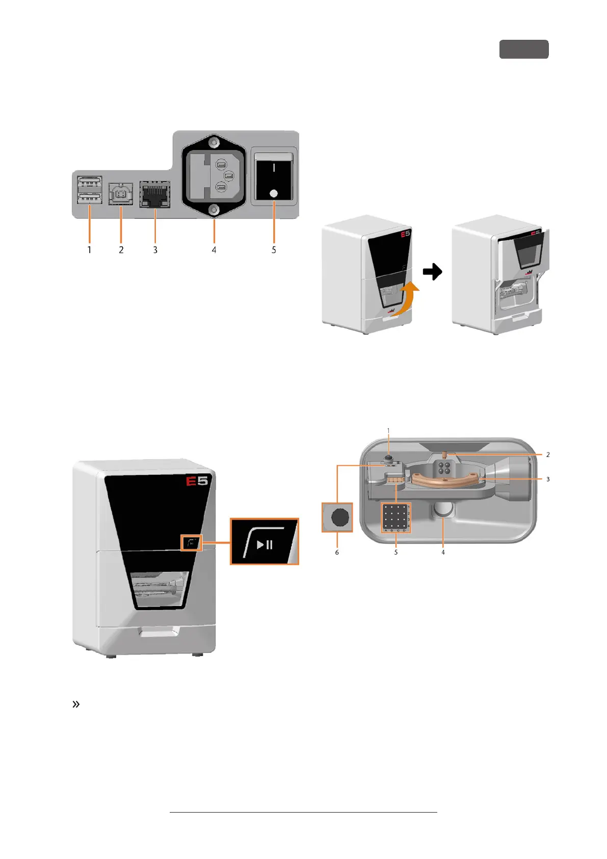
4.5 Working chamber door
The working chamber door locks the working chamber
and protects the user from injuries during operation.
You can open and close the working chamber door
manually.
You cannot open the door when the machine is
switched off or while the axes are moving.
FIG. 3
4.6 Working chamber
You can insert blanks and tools into the working
chamber. This is where the blanks are processed.
FIG. 4
1. Measuring key
Cleaning the machine (
page 44)
2. Spindle with collet chuck for picking up tools
Inserting and exchanging tools (
page 33)
3. Blank holder
Mounting & removing blanks (
page 27)
4. Suction opening for the air extraction system
Installing the air extraction system (
page 18)
5. Tool magazine
Inserting and exchanging tools (
page 33)
6. Insert for the AirTool
Inserting and exchanging tools (
page 33)
Get to know your machine
EN 11
Original Operating Instructions: E5
Version: 4/27/2023