3-32 How to Connect the Printer Components Rev AB
Videojet 8520 Operator Manual
2 Identify both ends of each printhead cable using the enclosed cable
markers and insert strips.
3 Check that all union nuts are securely fastened on the connectors.
Otherwise there is risk of data communication errors.
4 Make sure that the connector cable is laid at a sufficient distance from
all sources of interference. Do not lay the cable parallel to any
frequency converters or servo-motor cables.
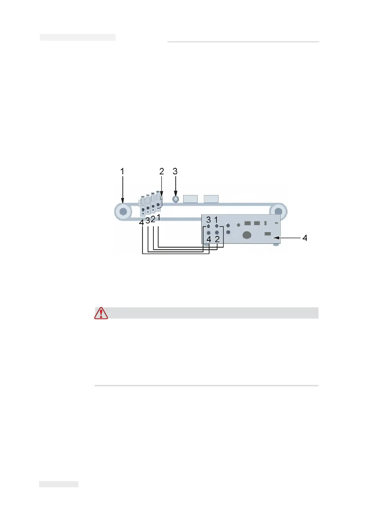
Figure 3-48 shows the connection of the connector cable from the
printhead to the controller.
PERSONAL INJURY. The controller must be switched off when the
printheads are being installed. For further information on the
positions of the printheads refer to “Positioning of Printhead” on
page 3-12.
In general, the controller must always be switched off before you
connect or disconnect any external items.
1. Back of the controller
2. Conveyor belt
3. Photoelectric cell
4. Shaft encoder
Figure 3-48: Connector Cable Connection