Rev AB Mounting of Controller 3-31
Videojet 8520 Operator Manual
Mounting of Controller
CLARiTY Controller
The CLARiTY operator interface can be mounted at a convenient location
so that the operator has adequate access to the panel. The CLARiTY
controller has a built-in power supply unit.
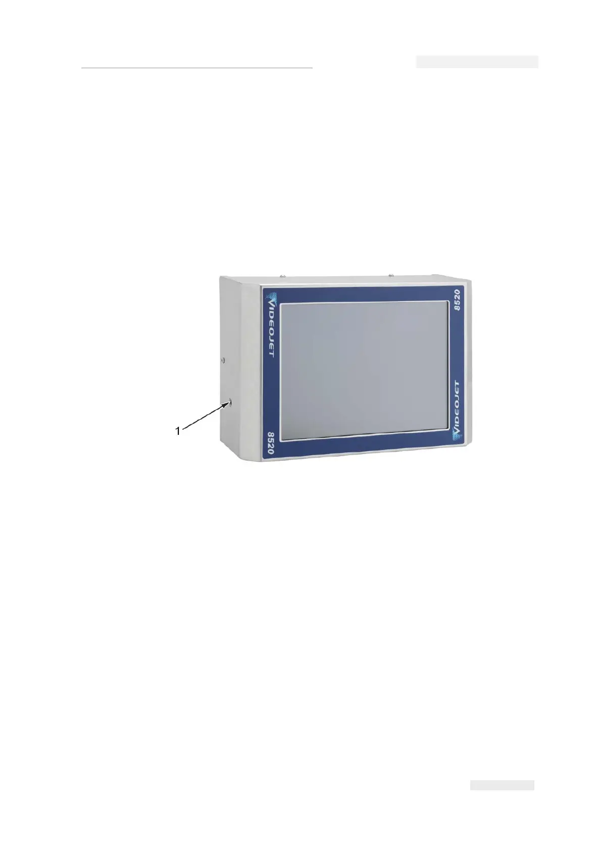
The unit has two M6 mounting holes located at both sides of the unit as
shown in Figure 3-47.
The CLARiTY controller can be mounted in any convenient location,
provided that the maximum lead length of 10 m is not exceeded. The
mounting brackets are connected to the controller with the help of knobs.
The bracket allows you to attach the controller as required to a suitable
location.
How to Connect the Printer Components
Do the following tasks to connect the printer components:
1 Do not connect the connector cable before the printheads, controller
and, if applicable, a shaft encoder have been installed on the
production line.
Figure 3-47: Controller
1. Mounting Hole (x2)