VIVOTEK - A Leading Provider of Multimedia Communication Solutions
User's Manual - 15
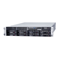
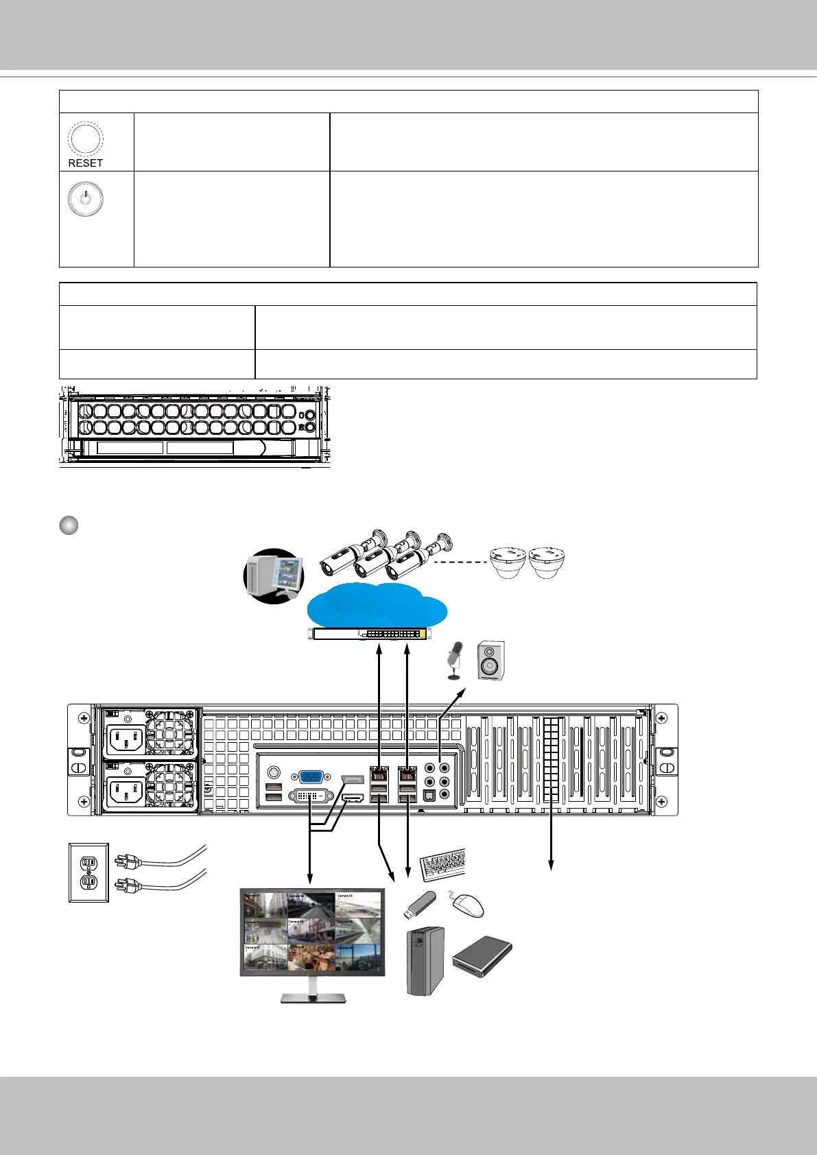
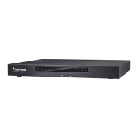
Rear View
Camera 01
Camera 02
Camera 03
Camera 04
Camera 06
Camera 05
Camera 07
Camera 08
Camera 09
LAN/WAN
AC100~240V
50/60Hz, 11-3.5A
NET1
NET2
VGA, DVI, Display
port, HDMI
Audio input &
output
USB 3.0 and 2.0
RAID card
Make sure you
connect both power
supplies to the mains.
Control Panel buttons and LEDs
Reset This button is used to reboot the system.
Power The main power switch is used to apply or remove power from
the power supplies to the server. Turning off system power
using this button removes the main power but keeps standby
power supplied to the system. You must unplug the system
before servicing components inside the chassis.
Drive Tray LEDs
Green When lit, indicates drive activity. Blinking indicates the drive is being
accessed.
Red Red indicates a SAS/SATA drive failure.