Home
Waters
Security Sensors
2489
Page 119
Waters 2489 - Page 119
234 pages
Manual
Save Page as PDF
To Next Page
To Next Page
To Previous Page
To Previous Page
Loading...
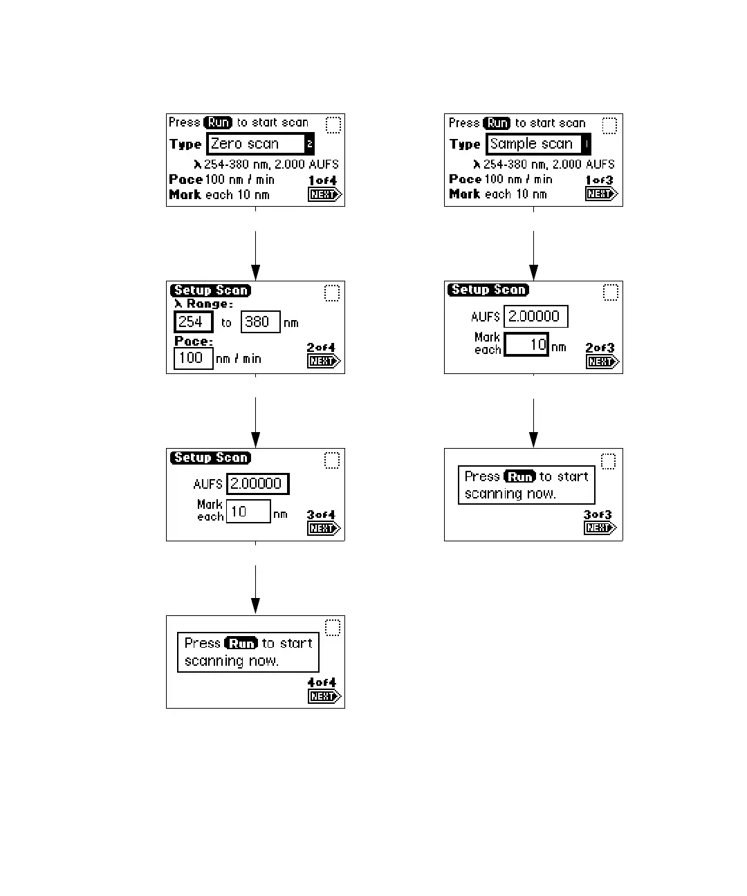
Scanni
ng spectra
3-5
1
Zero and sampl
e scan screen
Sample sc
an (Scr
een 1 o
f 3)
Sample sc
an (Scr
een 2 o
f 3)
Sample sc
an (Scr
een 3 o
f 3)
Zero scan
(Screen
3 of 4)
Zero scan
(Screen
4 of 4)
Zero scan
(Screen
2 of 4)
Zero scan
(Screen
1 of 4)
118
120
Table of Contents
Main Page
Default Chapter
9
Table of Contents
9
Theory and Principles of Operation
17
1 Theory and Principles of Operation
18
Detector Description
18
Detector Description
19
Principles of Operation
20
Detector Optics
20
Optics Assembly Light Path
21
Waters Taperslit Flow Cell
22
Filtering Noise
23
Wavelength Verification and Test
25
Operational Modes
27
Single Wavelength Mode
27
Primary Parameters
27
Secondary Parameters
28
Dual Wavelength Mode
28
Chart out Selection Modes
29
Spectrum Scanning
29
Cuvette Operations
30
Ratioplot
31
Maxplot
31
Thermal Wander Management
31
2 Installing the Detector
33
Preparing for Installation
34
Site Selection and Power Requirements
36
Site Selection
36
Power Requirements
37
Unpacking and Inspecting
37
Unpacking
38
Inspecting
38
Making Fluid Line Connections
38
Connecting Columns
39
Assembling the Fittings
40
Making Connections
41
Making Electrical Power Connections
41
Detector Rear Panel
42
Making Signal Connections
43
Making I/O Signal Connections
44
I/O Signals
45
Making Ethernet Connections
46
Making Ethernet Connections with Waters Data Systems
46
Starting a Method
48
Turning the Detector Lamp on or off
48
Connecting the Detector to a Separations Module
50
Generating Auto Zero
50
Generating Chart Mark on Inject
51
Connecting to Other Devices
52
Required Materials
53
Connecting the Cables
53
Connecting the Detector to Empower Using an E-SAT/IN Module
53
E-SAT/IN Module
53
Connecting the Detector to the E-SAT/IN Module
55
Connecting the Detector to a 745/745B/746 Data Module
57
Connecting the Detector to a Chart Recorder
59
Recorder Signal
59
Chart Marks
60
Connecting the Detector to the Waters 600 Series Pump
61
Fluid Line Connections
61
Lamp On/Off Connections
61
Auto Zero Connections
62
Chart Mark Connections
63
Inject Start Connections
64
Pump and Detector Inject Start Connections
65
Connecting the Detector to the Waters 717Plus Autosampler
65
Auto Zero Connections
66
Inject Start Connections
67
Connecting the Detector to a Fraction Collector
68
3 Preparing the Detector
69
Initializing the Detector
70
Diagnostic Test Failure
71
Using the Operator Interface
71
Using the Display
71
Absorbance and Message Icons
72
Using the Keypad
74
Navigating the User Interface
80
Navigating to and from the Absorbance Screen
80
Setting up a Run
81
Primary and Secondary Functions
82
Operating the Trace and Scale Functions
88
Operating Other Detector Functions
90
Configuring the Detector
90
Configuring Event Inputs (Contact Closures)
91
Setting Pulse Periods
92
Setting Display Contrast
93
Displaying System Info
93
Using Help
94
Operating the Detector
94
Overview of Detector Operation
94
Operating Modes
94
Stand-Alone Operation
95
Remote Control
95
Verifying the Detector
95
Before You Begin
95
Recording Sample and Reference Beam Energies
96
Verifying Peak Response
97
Wavelength Calibration
98
Operating the Detector in Single Wavelength Mode
99
Operating the Detector in Dual Wavelength Mode
100
Changing from Single to Dual Wavelength Mode
101
Obtaining a Ratioplot
102
Obtaining a Maxplot
103
Programming Timed Events, Threshold Events, and Methods
103
Timed Events
104
Threshold Events
107
Storing a Method
108
Retrieving a Method
109
Viewing Events Within a Method
110
Resetting a Method
110
Clearing Events
111
Scanning Spectra
112
Before You Begin
112
Scanning New Spectra
116
Zero Scan
117
Running the Sample Scan
120
Storing a Spectrum
124
Getting Information about a Stored Spectrum
124
Reviewing a Stored Spectrum
125
Subtracting a Spectrum
125
Replaying a Spectrum
126
Scanning Using the Cuvette
127
Before You Begin
128
Cuvette Scanning Procedure
128
Scanning Using a Flow Cell and a Syringe
130
Conserving Lamp Life
130
Shutting down the Detector
133
Removing Buffered Mobile Phase
133
4 Maintaining the Detector
135
Contacting Waters Technical Service
136
Maintenance Considerations
136
Safety Precautions
136
Spare Parts
136
Proper Operating Procedures
137
Removing the Front Left Panel Cover
137
Routine Maintenance
138
Maintaining the Flow Cell
138
Flushing the Flow Cell
139
Removing and Cleaning the Flow Cell
140
Disassembling and Reassembling the Flow Cell
140
Before You Begin
140
Tools Required
141
Removing the Flow Cell Assembly
141
Disassembling the Flow Cell
144
Inspecting, Cleaning, and Replacing Damaged Flow Cell Components
147
Rebuilding the Flow Cell
147
Replacing the Flow Cell
149
Replacing the Lamp
150
Lamp Characteristics
150
Lamp Energy and Performance
150
When to Replace the Lamp
151
Removing the Lamp
152
Installing the New Lamp
155
Recording the New Lamp Serial Number
157
Setting the Lamp Threshold
159
Replacing Fuses
160
5 Error Messages, Diagnostic Tests, and Troubleshooting
164
Error Messages
164
Startup Error Messages
164
Error Messages Preventing Operation
167
User-Selected Diagnostic Tests
170
Overview
170
Using the Diagnostic Tests
173
Contacting Waters Technical Service
173
Using the Sample and Reference Energy Diagnostic Tests
173
Using the Input & Output Diagnostic Tests
174
Displaying Auto Zero Offsets
175
Setting Fixed Absorbance Value
175
Setting Fixed Voltage Output
176
Using the Lamp, Display, and Keypad Diagnostic Tests
177
Using the Change Lamp Diagnostic Test
177
Using the Other Detector Diagnostic Tests
179
Service Diagnostic Tests
181
Troubleshooting
181
When You Contact Waters
181
Diagnostic Tests
182
Power Surges
182
Hardware Troubleshooting
182
A Safety Advisories
186
Warning Symbols
186
Task-Specific Hazard Warnings
186
Warnings that Apply to Particular Instruments, Instrument Components, and
187
Burst Warning
187
Mass Spectrometer Flammable Solvents Warning
187
Mass Spectrometer Shock Hazard
188
Biohazard Warning
188
Chemical Hazard Warning
189
Caution Symbol
189
Warnings that Apply to All Waters Instruments
189
Electrical and Handling Symbols
197
Electrical Symbols
197
Handling Symbols
198
B Detector Specifications
200
Operational Specifications
200
Optical Specifications
202
Optional Waters Taperslit Flow Cell Specifications
203
C Spare Parts
205
D Solvent Considerations
208
Introduction
208
Clean Solvents
208
Solvent Quality
208
Preparation Checklist
208
Water
208
Using Buffers
208
Tetrahydrofuran
209
Solvent Miscibility
209
How to Use Miscibility Numbers
211
Buffered Solvents
212
Head Height
212
Solvent Viscosity
212
Mobile Phase Solvent Degassing
212
Gas Solubility
213
Effects of Intermolecular Forces
213
Effects of Temperature
213
Effects of Partial Pressure
213
Solvent Degassing Methods
214
Sparging
214
Vacuum Degassing
214
Solvent Degassing Considerations
214
Vacuum Degassing
215
Wavelength Selection
215
UV Cutoffs for Common Solvents
215
Mixed Mobile Phases
215
Wavelength Selection for Chromophore Detection
217
Other manuals for Waters 2489
Overview And Maintenance Guide
150 pages
Quick Install Guide
4 pages
Related product manuals
Waters 2487
6 pages
Waters 2487 Dual A
232 pages
Waters 2414
130 pages
Waters 2475
228 pages
Waters 2998
122 pages
Waters 2996
84 pages
Waters Micromass ZQ 2000
133 pages
Waters 3100
220 pages
Waters ACQUITY QDa
104 pages
Waters Micromass ZQ 4000
133 pages
Waters ACQUITY RDa
107 pages