CHAPTER 6 - DETAILED PARAMETER DESCRIPTION
115
Range
[Factory Setting]
Parameter Unit Description / Notes
It selects the signal type of the current analog output AO2.
P255 0 to 1
AO2 Analog Output [ 0=0-20mA ]
Type (0 to 20)mA or -
(4 to 20)mA
P255 AO2 Output Type
0 (0 to 20)mA
1 (4 to 20)mA
For transforming the current analog output AO2 to a voltage output
of 0 to 10V, connect a resistor of 500Ω ± 1% 0.5W in parallel with
the output signal.
Remember when the output type is selected to (4 to 20)mA, this will
be the total range of the signal output.
0% of the signal = 4mA and 100% of the signal = 20mA.
Table 6.28 - AO2 signal type
Scale of the Analog Output indications:
- Full scale =10V: for Output AO1.
- Full scale =20mA for Output AO2.
Current (%In of the SSW)
Input Voltage (%Un of the SSW)
Output Voltage (%Un of the SSW)
Power Factor
Motor Thermal Protection
Power (W)
Power (VA)
Torque (% Tn Motor)
Fieldbus
Serial
SoftPLC
P251
P253
Gain
P252, P254
AO1
AO2
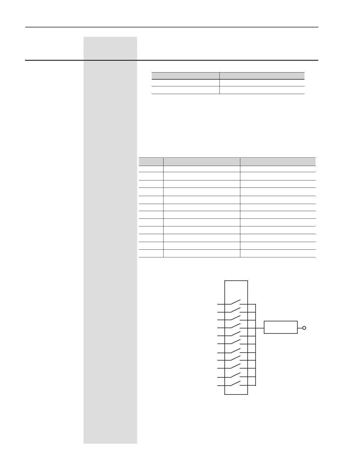
Figure 6.15 - Block diagram of the Analog Outputs
Table 6.29 - Functions of the Analog Outputs
P251/P253 Function of the Analog Output Full Scale When
0 Not used -
1 Current in % In of the SSW 5 x P295
2 Input Voltage in % Un of the SSW 1.5 x P296(max.)
3 Motor Voltage in % Un of the SSW 1.5 x P296(max.)
4 Power Factor P008 = 1.00
5 Thermal Protection P050 = 250%
6 Power in W 1.5 x √3 x P295 x P296(max.)
7 Power in VA 1.5 x √3 x P295 x P296(max.)
8 Torque in % Tn of the Motor 5 x P009 = 100%
9 Fieldbus 16383 (3FFFh)
10 Serial 16383 (3FFFh)
11 SoftPLC 16383(3FFFh)


 To Next Page