CHAPTER 6 - DETAILED PARAMETER DESCRIPTION
114
Range
[Factory Setting]
Parameter Unit Description / Notes
NOTES!
1. Set P277=4 (FWD/REV-K1) and P278=4 (FWD/REV-K2)
before connecting the power supply.
2. The method used to start the motor to a new direction of
rotation will be the same as the one set to start the motor
forthersttime.
3. The motor will start again only after the time set at P630
(time delay after stopping) has reached zero.
4. See the recommended setup at items 3.3 and 3.3.8.
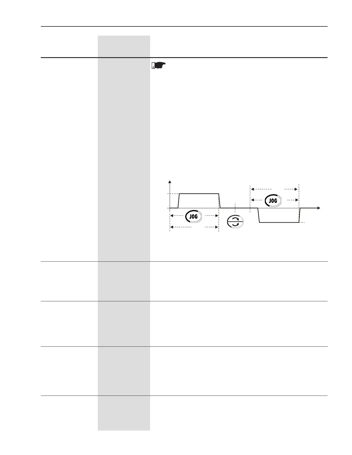
“JOG Only”
This option allows the slow speed with Jog in both forward and re-
verse directions without auxiliary contactors connected at the input
power supply.
See more information at P510 and P511 parameters.
Figure 6.14 - Motor direction of rotation with “Jog only”
U(V)
0
P511
P102
P102
P511
t(s)
Checkpossibleoptionsintable6.29andgure6.15.
AO1=10V when the values shown in table 6.29 are on the full scale
and P252=1.000.
P251 0 to 11
AO1 Output Function [ 0=Not Used ]
(0 to 10)V -
Sets the gain of the analog output AO1.
For P252=1.000 the value of output AO1 is set according to the
descriptioningure6.15.
P252 0.000 to 9.999
AO1 Analog Output [ 1.000 ]
Gain 0.001
Checkthepossibleoptionsintable6.29andgure6.15.
AO2=20mA when the values shown in table 6.29 are on the full scale
and P254=1.000.
P253 0 to 11
AO2 Analog Output [ 0=Not Used ]
Function -
(0 to 20)mA or
(4 to 20)mA
Sets the gain of the analog output AO2.
For P254=1.000 the value of output AO2 is set according to the
descriptioningure6.15.
P254 0.000 to 9.999
AO2 Analog Output [ 1.000 ]
Gain 0.001


 To Next Page