170 RT System 2 v2.3 Deployment Guide R01.i
© 2010-2014 Wireless Seismic, Inc. All rights reserved.
D. LED Indicators
WRU Deploying
If power is removed from a WRU in the deploying state, the WRU stays in the deploying state
and restarts the deploying process when power is restored.
After removing both batteries from a deploying WRU, and then replacing BAT A, BAT B, or
both, when the first battery is connected, the WRU goes through the power on LED
sequence. If both batteries are connected, the battery fuse test is executed. If only one
battery is connected, the battery fuse test is skipped. The remainder of the self-tests are
then executed.
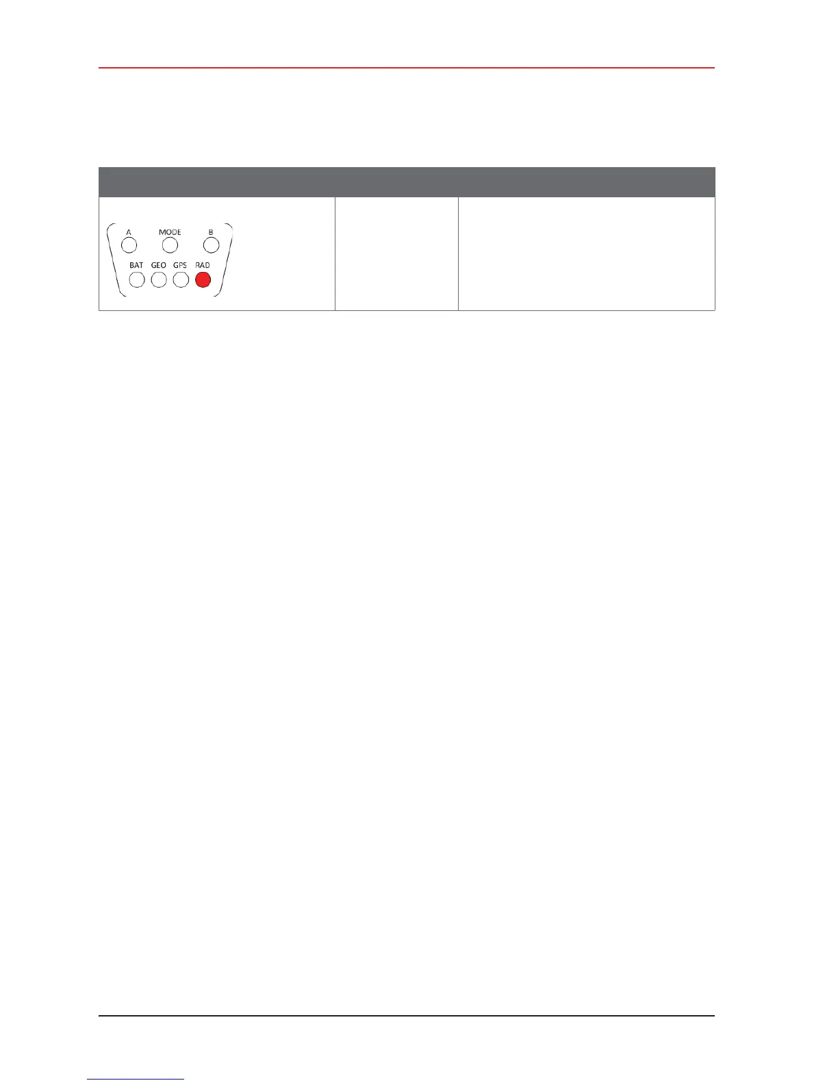
The following table shows the LED power-on sequence for an deploying WRU:
No neighbor
detected
RAD Solid
If this is the first WRU deployed, this is the
expected condition.
Table D–3 WRU LED Indications, Deploying Sequence (cont.)
LED Indicators Summary Description