R01.i RT System 2 v2.3 Deployment Guide 67
© 2010-2014 Wireless Seismic, Inc. All rights reserved.
4. Point-to-Point Backhaul
Overview
The radios are configured as pairs and are either an Access Point (A) or a Station (S).
An Access Point communicates only with a Station. An Access Point cannot communicate with
an Access Point, and a Station cannot communicate with a Station.
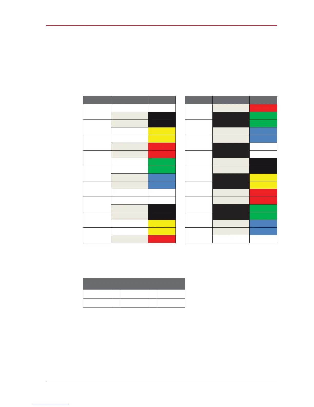
The poles (masts) and radios for a six-channel system are labeled and color-coded as
follows. The number of colors used should match the number of channels used.
Where:
i Label Nomenclature:
i S = Station
i A = Access Point
i The pole pairs must remain in sequential order:
Ɣ Radio 1:A-P1 communicates only with Radio 1:S-P2
Ɣ Radio 2:A-P2 communicates only with Radio 2:S-P3
Ɣ And so on until pole 18, where Radio 18:A-P18 communicates only with Radio 18:S-
P1
Pole Radio Color Pole Radio Color
Pole 1
18:S-P1 White
Pole 10
9:S-P10 Red
1:A-P1 Black 10:A-P10 Green
Pole 2
1:S-P2 Black
Pole 11
10:S-P11 Green
2:A-P2
Yellow 11:A- P11 Blue
Pole 3
2:S-P3
Yellow
Pole 12
11:S-P12 Blue
3:A-P3 Red 12:A-P12 White
Pole 4
3:S-P4 Red
Pole 13
12:S-P13 White
4:A-P4 Green 13:A-P13 Black
Pole 5
4:S-P5 Green
Pole 14
13:S-P14 Black
5:A-P5 Blue 14:A-P14 Yellow
Pole 6
5:S-P6 Blue
Pole 15
14:S-P15 Yellow
6:A-P6 White 15:A-P15 Red
Pole 7
6:S-P7 White
Pole 16
15:S-P16 Red
7:A-P7 Black 16:A-P16 Green
Pole 8
7:S-P8 Black
Pole 17
16:S-P17 Green
8:A-P8
Yellow 17:A-P17 Blue
Pole 9
8:S-P9 Yellow
Pole 18
17:S-P18 Blue
9:A-P9
Red 18:A-P18 White
Table 4–1 Label Nomenclature
Pair # : A or S - Pole #
2:A-P2
2:S-P3