44 RT System 2 v2.3 Deployment Guide R01.i
© 2010-2014 Wireless Seismic, Inc. All rights reserved.
3. Backhaul
Backhaul Components
3.2.6 Radio Antennas
The following table lists the supported antennas for the radios:
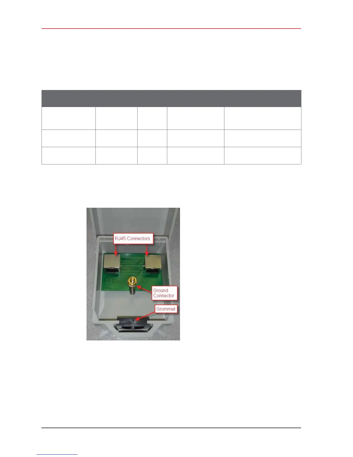
3.2.7 Surge Protector Box
The following figure illustrates the inside of the Surge Protector Use a surge protector on
each mast between the Rocket radio or the NanoStation radio and the LIU.
Table 3–5 Antenna Specifications, Radios
Model
Frequency
(MHz)
Gain
Dimension (Length
x Diameter)
See
WSI 65-0178
2x2 Dual Polarity
MIMO Omni
5450 - 5850 13 dBi 6.2x3.8x32.8 in
158x98x834 mm
“Rocket Recorder Antenna” on
page 152
WSI 65-0179
Omni
5275 - 5850 6 dBi 10.6 in
269 mm
“Bullet Line Station Antenna”
on page 149
WSI 65-0177
Antenna Panel
5150 - 5825 19 dBi 7.5 x 7.5 x 0.8 in
190 x 190 x 20 mm
“Bullet Line Station Antenna”
on page 149
Figure 3–13 Surge Protector
Connections