July 2019
6-12
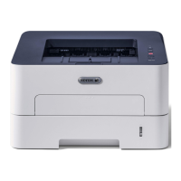
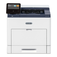
Xerox® B210 Service Manual
GP 6, GP 7
Initial Release
General Procedures - Information
GP 6 Firmware Upgrade
Purpose
The following procedure is to be used for upgrading the firmware of the B210 single function
printer.
Xerox CentreWare Internet Services (CWIS) Firmware Upgrade
NOTE: Depending on the internet browser used, the vebiage may vary. The following proce-
dure was created using the Chrome
®
internet browser.
1. Download the latest Firmware file from Xerox.com.
2. Type the machine IP address in the browser address line to reach machine's CWIS hom
e
scr
een.
3. Select the Pr
operties tab.
4. On the left hand side of the screen, scroll down the list, then select Mai
ntenance:
a. Login to CWIS with username [a
dmin] and password.
NOTE: The default administrator password is the entire device serial number. It ma
y
be
necessary to obtain the password from the customer if it has been changed.
b. Select U
pgrade Management, the [Enabled] box must be checked.
c. In the list on the left, above Upgr
ade Management, select Firmware Upgrade.
5. Select C
hoose file.
6. Browse to the Firmware file downloaded, click on Op
en. You will see the file name in the
scr
een.
7. Select I
nstall Software.
8. A dialog box appears asking “Do you really want to upgrade?”, Select OK.
a. A Firmware gas gauge will appear and increment.
b. Processing upgrade will appear next, it can take more than a minute.
c. The LED lights will blink, the the machine print a configuration page.
9. Check the configuration page that prints to make sure that the Firmware upgr
ade was
succ
essful.
10. The CWIS under Ge
neral Setup > Configuration > Printer Setup. The line [System
So
ftware Version] should reflect the latest software just installed.
GP 7 Usage of the Electrostatic Discharge (ESD) Field
Service Kit
Purpose
The purpose of the Electrostatic Discharge (ESD) Field Service Kit is to preserve the inherent
reliability and quality of sensitive electronic components handled by the service representative.
The kit should be used whenever handling the circuit boards or any other ESD sensitive com-
ponents.
Procedure
1. Switch off the machine, then disconnect the machine power cord.
2. Assemble the kit:
a. Place the static dissipative work surface mat on a flat surface in close proximity to
t
he machine or the component
b. Connect the snap end of the green grounding cord to the snap on the static dissipa-
tive work surface mat. Connect the male end (plug) to the frame.
c. Connect the small snap end of the blue cord to the top snap on the gr
een grounding
cord
.
d. Connect the small snap end of the blue cord to the snap on the adjustable cloth wrist
st
rap or the ESD wristwatch.
e. Install the adjustable wrist strap or ESD wristwatch securely on the wrist.
3. The circuit boards (PWB’s) and ESD sensitive components can now be handled without
caus
ing any ESD related damage. Place all of the components removed from t
he
mac
hine onto the static dissipative work surface mat.
4. New replacement components, as well as defective components, should be handled dur-
ing unpacking and repacking using the ESD Field Service Kit. During transfer from or to
t
he packing material or container, the PWB should be placed on the static dissipative work
surface mat.
 Loading...


