July 2019
4-41
Xerox® B210 Service Manual
REP 4.17, REP 4.18
Repairs - Adjustments
Initial Release
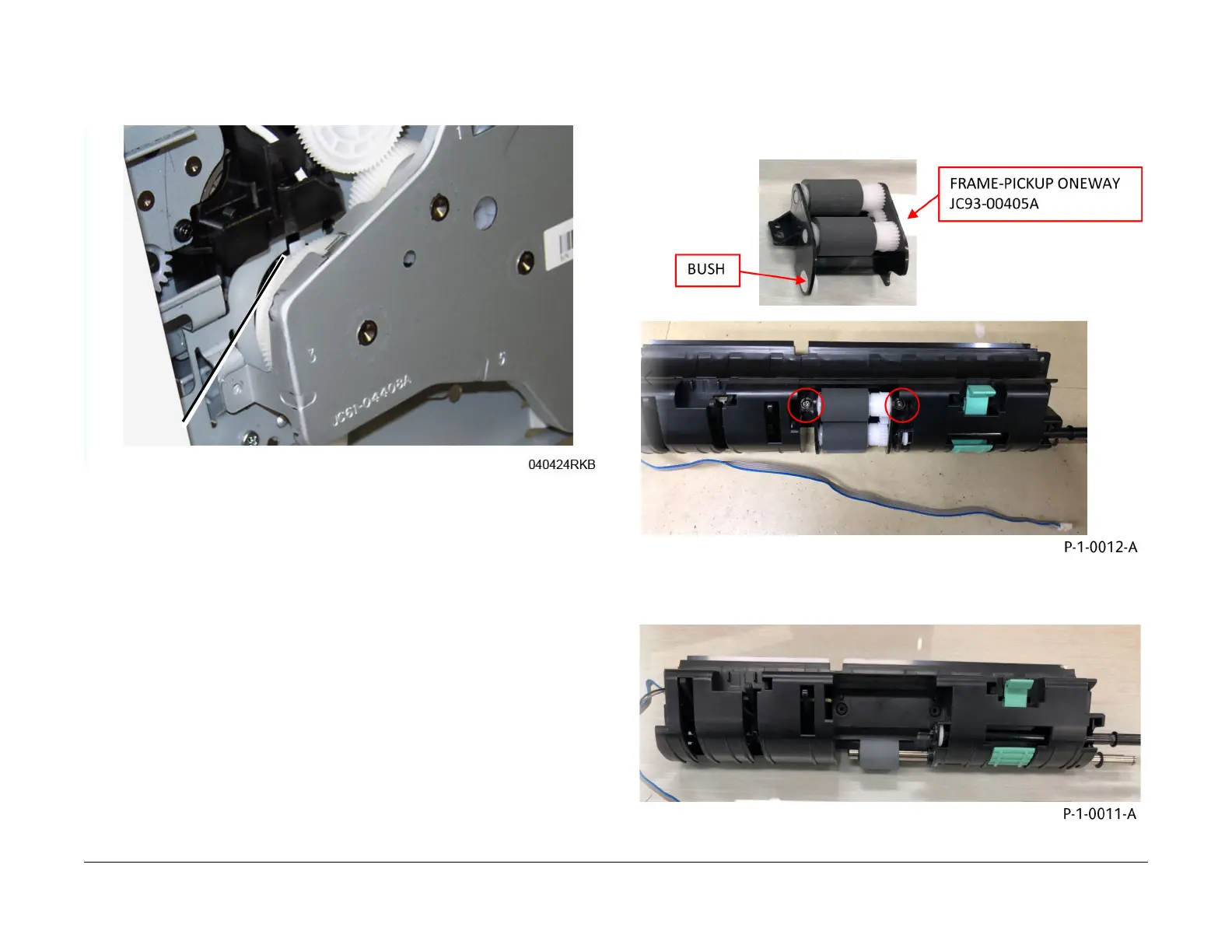
3. Lock lever alignment, Figure 3:
a. Align the two locking lever tabs to the cutouts in the frame
b. Move the locking lever to the lock position (left) to insert the tabs into the cutouts.
Figure 3 Locking Lever Tab and Frame Cutout
4. Install the remaining components in the reverse of the removal procedure.
REP 4.18 Pick Up Assembly
Parts List on PL 4.5
Removal
1. Remove two screws, remove the one-way pickup frame from the upper pickup guide, then
rem
ove the bushing from the one-way pickup frame, Figure 1
.
Figure 1 One-way pickup frame and bushing removal
2. Remove the pickup guide from the upper pickup guide, F
igure 2.
Figure 2 Pickup guide removal
Locking Lever
Tab and Cutout
 Loading...