July 2019
4-30
Xerox® B210 Service Manual
REP 4.11, REP 4.12
Initial Release
Repairs - Adjustments
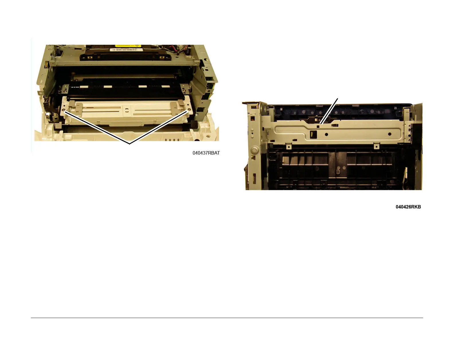
4. Remove two screws securing the top of the Manual Paper Tray, then remove the Manual
P
aper Tray, Figure 2
.
Figure 2 Manual Paper Tray Top Screws (Top View)
Replacement
Replacement is the reverse of the removal procedure.
REP 4.12 Exit Sensor
Parts List on PL 4.1
Removal
1. Switch off the machine, then disconnect the power cord.
2. Remove the Left and Right Side Covers, RE
P 2.2.
3. Remove the Rear Cover, REP 2.3.
4. Remove the Fuser, REP 5.1.
5. Release the latch on the underside of the frame to release the Exit Sensor Mounting Plate
f
rom the frame, Figure 1
.
Figure 1 Exit Sensor Plate Latch Release (Bottom View)
 Loading...