July 2019
4-19
Xerox® B210 Service Manual
REP 4.7, REP 4.8
Repairs - Adjustments
Initial Release
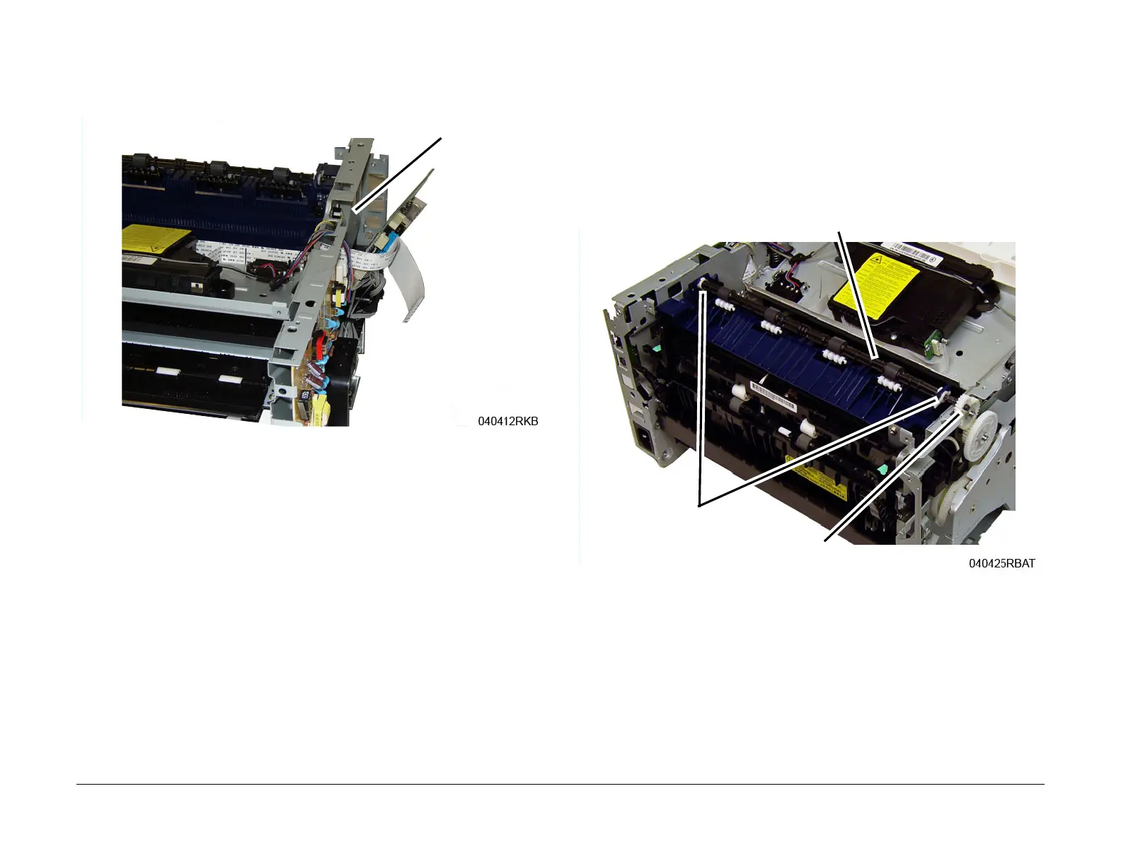
4. Remove the Output Tray Full Sensor, Figure 2:
a. Disconnect the connector from the Output Tray Sensor.
b. Unlatch, then remove the Output Tray Sensor.
Figure 2 Output Tray Full Sensor (Top Right View)
Replacement
Replacement is the reverse of the removal procedure.
NOTE: When installing the Main PWB, make sure the ground screw with large head is installed
in t
he correct location.
REP 4.8 Exit Roll and Bushings
Parts List on PL 4.3
Removal
1. Switch Off the Printer and unplug the Power Cord.
2. Remove the Top Cover, RE
P 3.2.
3. Remove the Exit Roll and Bushings, Figure 1:
a. Remove the Drive Gear.
b. Release the latch, rotate the bushing, then remove the bushings.
c. Remove the Exit Roll.
Figure 1 Exit Roll and Bushing (Top View)
Replacement
Replacement is the reverse of the removal procedure.
Exit Roll
Bushings
Driver Gear
 Loading...