July 2019
4-18
Xerox® B210 Service Manual
REP 4.6, REP 4.7
Initial Release
Repairs - Adjustments
Replacement
Replacement is the reverse of the removal procedure.
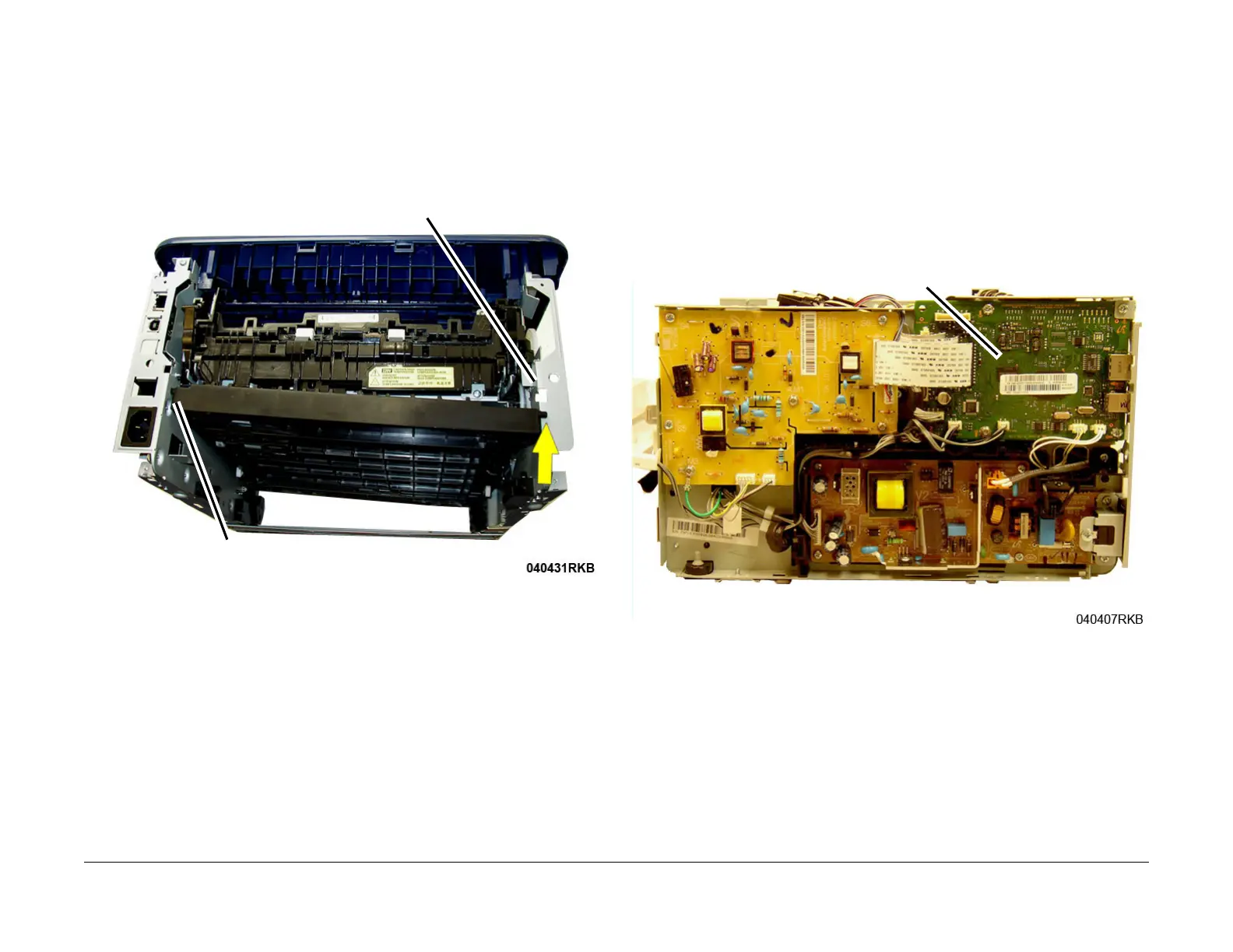
Replace the Duplex as follows, F
igure 2:
1. Insert the pivot on the left side into the hole.
2. Insert the right pivot into the frame cutout.
3. Lift and latch the front of the Duplex Assembly into position.
Figure 2 Duplex Assembly Pivots (Rear View)
REP 4.7 Output Tray Full Sensor
Parts List on PL 4.3
Removal
1. Switch off the machine, then disconnect the power cord.
2. Remove the Top Cover, RE
P 3.2.
NOTE: Do not disconnect the connectors to the Main PWB. The PWB only needs to be moved
away from the frame to access the Output Tray Full Sensor.
NOTE: Mark the location of the Ground Screw, with larger head, so it can be re-installed in the
corr
ect location.
3. Remove five screws, then move the Main PWB out of the way, Fi
gure 1.
Figure 1 Main PWB
 Loading...