December 2006
4-5
WorkCentre M20, 4118, FaxCentre 2218 Family
REP 1.2, REP 1.3
Repairs and Adjustments
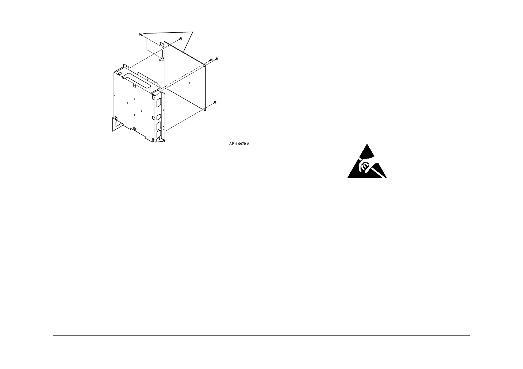
6. Remove the PBA main, Figure 2.
Figure 2 PBA main removal
Replacement
1. Replacement is the reverse of the removal procedure.
2. If a new PBA main has been installed, perform the following:
a. A memory clear, GP 5.
b. Re-enter the machine serial number. Refer to GP 6 Maintenance.
c. Use the information on the System Data list and Connect Page (M20i) list to re-enter
the customers settings. Refer to GP 2 User Mode Entry.
d. Go to GP 3, Service Mode Entry. Scroll to System Admin Tools/Maintenance. Per-
form the Adjust Shading procedure.
REP 1.3 PBA Main (4118/2218)
Parts List on PL 1.15 and PL 1.20
Removal
WARNING
Switch off the electricity to the machine. Disconnect the power cord from the customer
supply while performing tasks that do not need electricity. Electricity can cause death or
injury. Moving parts can cause injury.
WARNING
Take care during this procedure. Sharp edges may be present that can cause injury.
CAUTION
Before performing this procedure, refer to General Disassembly Precautions, GP 10.
NOTE: This procedure should only be performed on the 4118 and 2218. For the M20F PBA
Main repair procedure, go to REP 1.2.
NOTE: If necessary, refer to GP 20 for the acronym list and cross reference lists of more com-
monly recognised part names.
CAUTION
Ensure that E.S.D. procedures are observed during the removal and installation of the PBA
main.
1. If a new PBA main is to be installed, go to GP 2. Print the System Data list and Connect
Page list.
2. Remove the MEA unit - rear cover, REP 4.2.
3. Disconnect the CNs from the PBA main.
4. If installed, remove the following components:
• PBA LUI, PL 1.15 Item 11
• PBA SUB NIC, PL 1.15 Item 17
• PBA foreign device interface, PL 1.15 Item 18
• PBA foreign device interface harness, PL 1.15 Item 19
Remove 6 screws, then
the PBA main.