December 2006
6-58
WorkCentre M20, 4118, FaxCentre 2218 Family
GP 19, GP 20
General Procedures and Information
The following explains how the fixed lamp control circuit works. Logic unit "fuser on" sends trig-
ger current to triac driver PC3 LED, then the infrared ray is detected by PC3 photo detector.
Next, YC3 triac is conducted. The conducted current sends trigger input to triac SY1 gate. At
this point, SY1 is conducted and AC power is supplied to fixed lamp. Lamp is turned on
and temperature rises.
As this fixed lamp control circuit uses the AC voltage ("+" and "-" are repeated) as the power
supply, it used two-way triac (SY1), which has advantage over one-way SCR considering the
price, size and reliability.
The triac's gate can be triggered by either forward or reverse signal. Once triac is turned on, it
will not be controlled by gate signal, but will be continuously on until the current between major
terminals decreases below the holding current. In other words, you cannot turn it off with
reverse signal unlike SCR. This property is called current-voltage threshold rise rate (com-
mutation: dv/dt). In AC power control application, triac has to turn off conduction in each zero
crossing or switch it twice in each cycle. This switching operation is called commutation. It is
possible to turn off the triac at the end of half cycle by eliminating the gate signal when the load
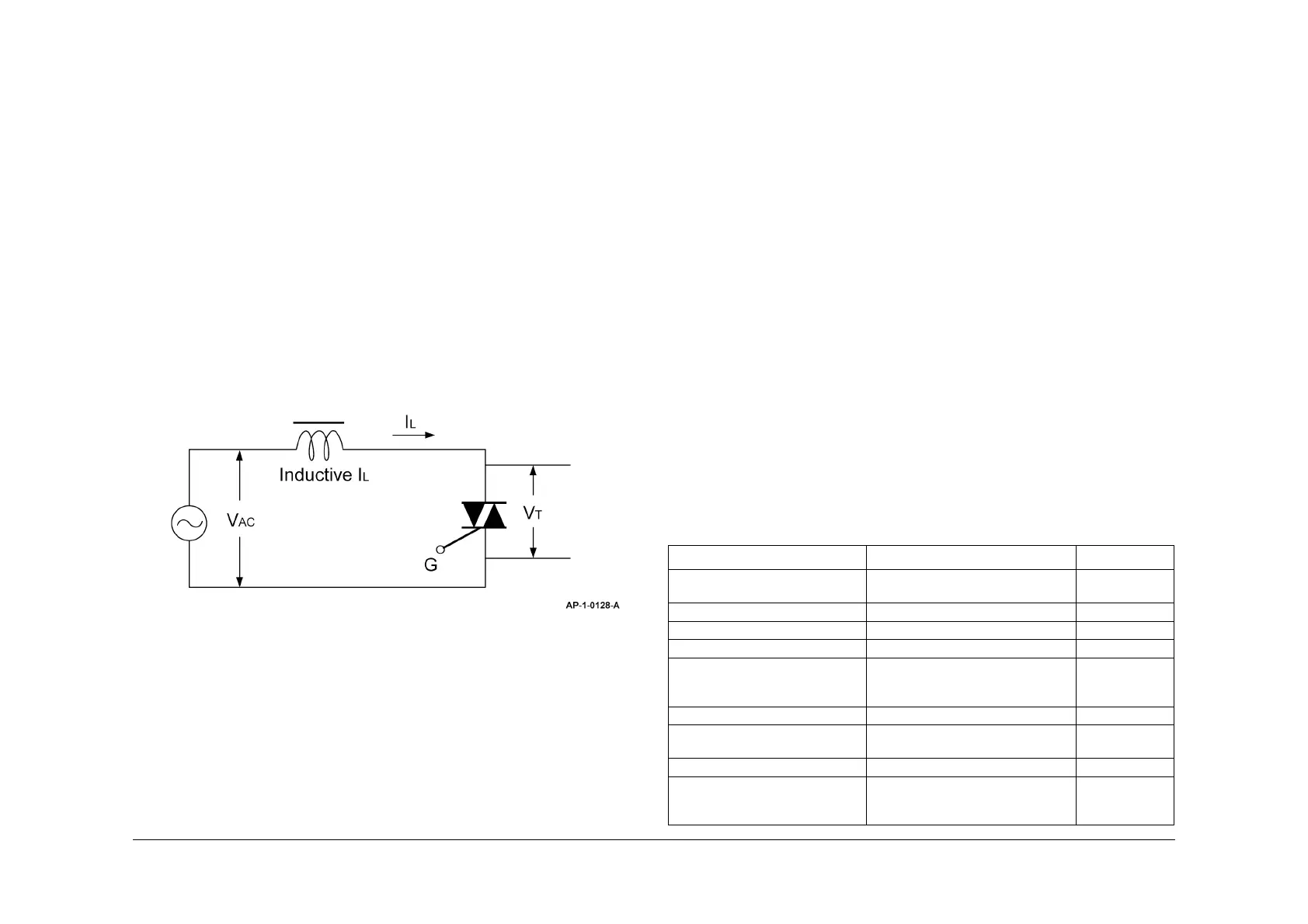
current (IL) is gained at the level equal to or lower than holding current. When triac commutes
off-line, the direction of the voltage of the both ends of triac will be reversed and increase up to
the maximum value of line voltage (VAC). At this point, the width of rise rate will be determined
by dv/dt and overshoot voltage, by the circuit. When triac commutes off-line, the voltage of both
ends of triac will have the same voltage as the line voltage. Refer to Figure 2.
Figure 2 Inductive circuit
GP 20 Acronyms and Parts Description List
Purpose
To provide a list of acronyms used throughout this service manual with an explanation of their
meaning. Refer to Table 1.
To also provide a cross reference list of part descriptions used throughout this service manual
with a list of more commonly recognised part descriptions. Refer to the relevant section:
• SMPS and PBA Main
• OPE Assembly
• Frames, Drives and Covers
•DADF
•ADF
•LSU
• Cassette Assembly
•SCF
• Side Cover Assembly
• Feeder Assembly
• MP Assembly
• Pickup Assembly
• Toner, Drum Cartridge and Fuser
• Exit Assembly
• Scanner Assembly
NOTE: All tables have the items listed in parts list order.
Acronyms
Refer to Table 1.
Table 1 Acronyms
Acronym Description PL Ref.
A/S material - dummy upper
assembly
A/S - After - service PL 14.10 Item 3
A/S material pickup, MP A/S - After service PL 8.20 Item 27
CBF - harness - main - MHV wire MHV - High voltage (charge voltage) PL 4.15 Item 10
CBF - harness - main - THV wire THV - Transfer high voltage PL 4.15 Item 9
CBF harness - LIU GND LIU - Line interface unit for FAX
GND - Ground
PL 1.10 Item 2
PL 1.15 Item 7
PL 1.20 Item 7
CBF harness - LSU LSU - Laser scanning unit PL 6.10 Item 2
CBF harness - OPC GND OPC GNG - Organic photo conduc-
tive ground
PL 4.10 Item 16
CBF harness - OPE OPE - Operation panel (control panel) PL 14.11 Item 18
CBF power switch grey CBF - Cable form PL 1.10 Item 2
PL 1.15 Item 2
PL 1.20 Item 2