December 2006
4-51
WorkCentre M20, 4118, FaxCentre 2218 Family
REP 10.2
Repairs and Adjustments
REP 10.2 MEC - Exit Assembly
Parts List on PL 10.10
Removal
WARNING
Switch off the electricity to the machine. Disconnect the power cord from the customer
supply while performing tasks that do not need electricity. Electricity can cause death or
injury. Moving parts can cause injury.
WARNING
Take care during this procedure. Sharp edges may be present that can cause injury.
CAUTION
Before performing this procedure, refer to General Disassembly Precautions, GP 10.
NOTE: If necessary, refer to GP 20 for the acronym list and cross reference lists of more com-
monly recognised part names.
1. Remove the ELA HOU - scanner assembly, perform REP 14.1 steps 1 through 7.
2. Open the ELA HOU - side cover assembly, PL 8.10 Item 1 and the MEA unit - cover front
assembly, PL 4.25 Item 6.
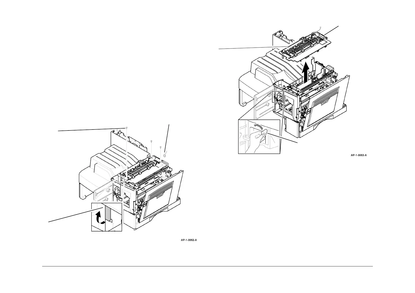
3. Prepare to remove the MEC - exit assembly, Figure 1.
Figure 1 Preparation
4. Remove the MEC - exit assembly, Figure 2.
Figure 2 MEC - exit assembly removal
Replacement
Replacement is the reverse of the removal procedure.
Disconnect
CN6 (M20F),
CN25 (4118) or
CN10 (2218).
2
Remove 3 screws.
3
Unclip the front of the
MEC - exit assembly.
1
Release the
harnesses.
2
Ensure the rollers are
raised.
3
Remove the
MEC - exit
assembly.