7-25
E
BRKT
POWER TRIM AND TILT UNIT
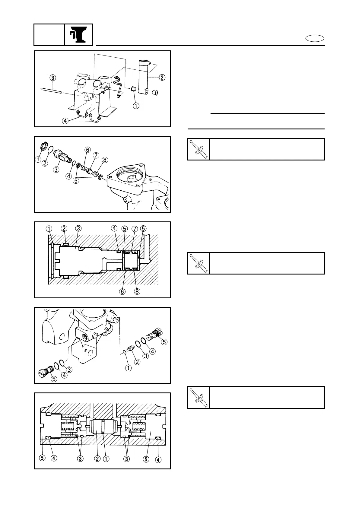
1. Install the tilt-cylinder and the delivery
pipes.
1 Bushing
2 Tilt-cylinder
3 Lower mount pin
4 Delivery pipe
NOTE:
Feed oil into each pipe.
2. Install the manual-valve in the body
with new O-rings.
1 Snap ring
2 O-ring
3 Manual release screw
4 O-ring
5 Manual valve seat
6 Manual release spring (ø0.6 mm)
7 Adapter 1
8 Manual release spring (ø1.2 mm)
T
R
.
.
Lock nut (delivery pipe):
15 Nm (1.5 m • kg, 11 ft • lb)
T
R
.
.
Manual valve:
3 Nm (0.3 m • kg, 2.2 ft • lb)
3. Install a new O-ring on the shuttle-pis-
ton and insert the piston into the body,
then install the main valves with new O-
rings.
1 O-ring
2 Shuttle-piston
3 O-ring
4 O-ring
5 Main valve
T
R
.
.
Main valve:
11 Nm (1.1 m • kg, 8.0 ft • lb)