7-26
E
BRKT
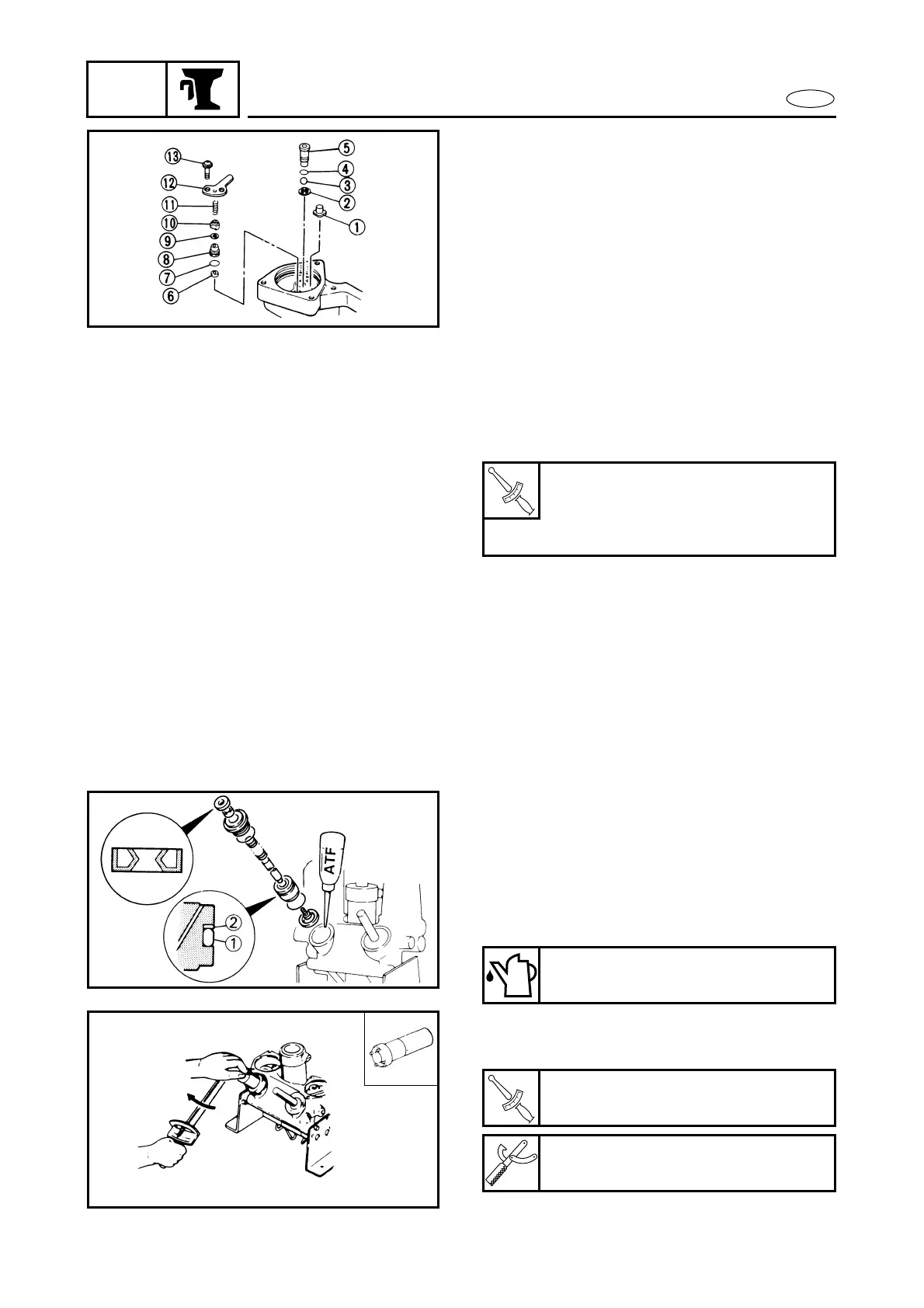
POWER TRIM AND TILT UNIT
4. Install the up-relief valve and the valve
lock screw with new O-rings and tighten
the screw to the specified torque.
1 Main valve seal
2 Washer
3 Ball
4 O-ring
5 Valve lock screw
6 Filter
7 O-ring
8 Up relief valve seat
9 Up relief valve seal
0 Valve support pin
A Up relief spring
B Trim spring
C Screw
T
R
.
.
Valve lock screw:
4 Nm (0.4 m • kg, 2.9 ft • lb)
Screw:
4 Nm (0.4 m • kg, 2.9 ft • lb)
5. Fit a new O-ring and the back-up ring on
the trim-piston, fit new O-rings and a
new oil-seal on the end-screw and
install the complete trim-piston in the
cylinder. Fill the cylinder with hydraulic
fluid and install and tighten the end-
screw to the specified torque.
1 O-ring
2 Back-up ring
ATF
(automatic transmission fluid)
T
R
.
.
End-screw (trim cylinder):
160 Nm (16 m • kg, 115 ft • lb)
Cylinder end screw wrench:
YB-6175-1A/90890-6548