7-27
E
BRKT
POWER TRIM AND TILT UNIT
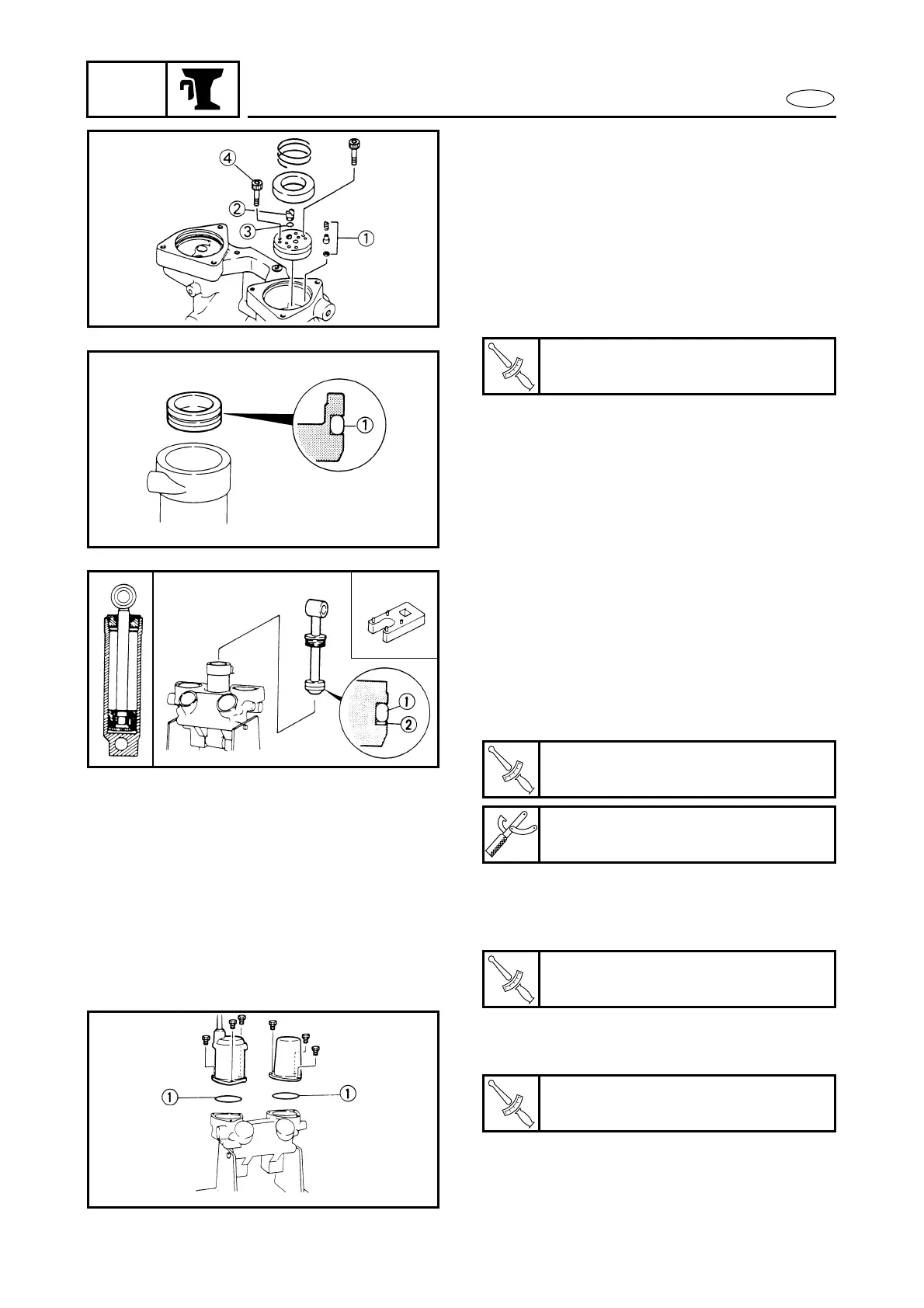
6. Install the down relief-valve and the
gear-pump complete with new O-rings,
tighten the bolts, and fit the connector-
shaft and filter, then fill with hydraulic
fluid.
1 Down relief-valve assembly
2 Shaft-connector
3 O-ring
4 Bolt
7. Fit a new O-ring on the free-piston and
install it into the cylinder.
1 O-ring
T
R
.
.
Bolt:
4 Nm (0.4 m • kg, 2.9 ft • lb)
8. Fit a new O-ring and the back-up ring to
the tilt-piston and install the piston in
the cylinder. Fill the cylinder with
hydraulic fluid and tighten the end-
screw to the specified torque.
1 O-ring
2 Back-up ring
9. Align the connector-shaft keyway with
the motor-shaft projection and install
the motor with a new O-ring.
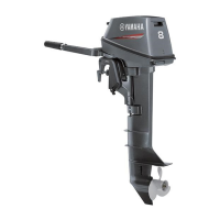
10. Install the hydraulic-fluid reservoir with
a new O-ring.
1 O-ring
T
R
.
.
End-screw (tilt cylinder):
90 Nm (9.0 m • kg, 65 ft • lb)
Cylinder end screw wrench:
YB-6175-2B/90890-06544
T
R
.
.
Bolt (tilt motor):
4 Nm (0.4 m • kg, 2.9 ft • lb)
T
R
.
.
Bolt (reservoir body):
7 Nm (0.7 m • kg, 5.1 ft • lb)