8-9
–+
ELEC
E
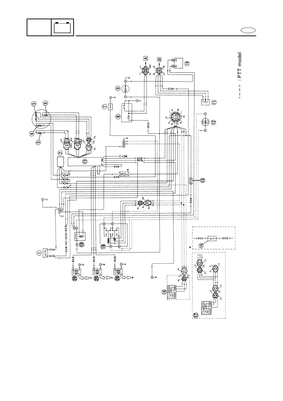
WIRING DIAGRAM
M30000-0
75, 80, 90 hp
1 Thermo switch
2 Rectifier/regulator
3 Crank position sensor
4 Lighting coil
5 Charge coil
6 Pulser coil
7 Electrothermal valve
(except for C75TR)
8 Oil level sensor
(oil injection model)
9 Starter motor
0 Battery
A Trim sensor (PTT model)
B Power trim and tilt motor
(PTT model)
C Fuse (20A)
D Neutral switch
(P75TH/75CEHTO, 90AEHD,
90TR/90AETO, B90TR/90AETO)
E CDI unit
F Trailer switch (PTT model)
G Power trim and tilt switch
(P75TH/75CEHTO)
H Power trim and tilt relay
(PTT model)
I Starter relay
J Ignition coil
Å To oil level gauge
ı To trim gauge
B......... Black
Gr ....... Brown
G ........ Green
Gy ...... Gray
L ......... Blue
Lg ....... Light green
O ........ Orange
P ......... Pink
R......... Red
Sb ...... Sky blue
W ....... White
Y ........ Yellow
 Loading...