B95W
Transport
08_Transport_en.fm - V1.0 - 1.8.17
265 / 306
8
27
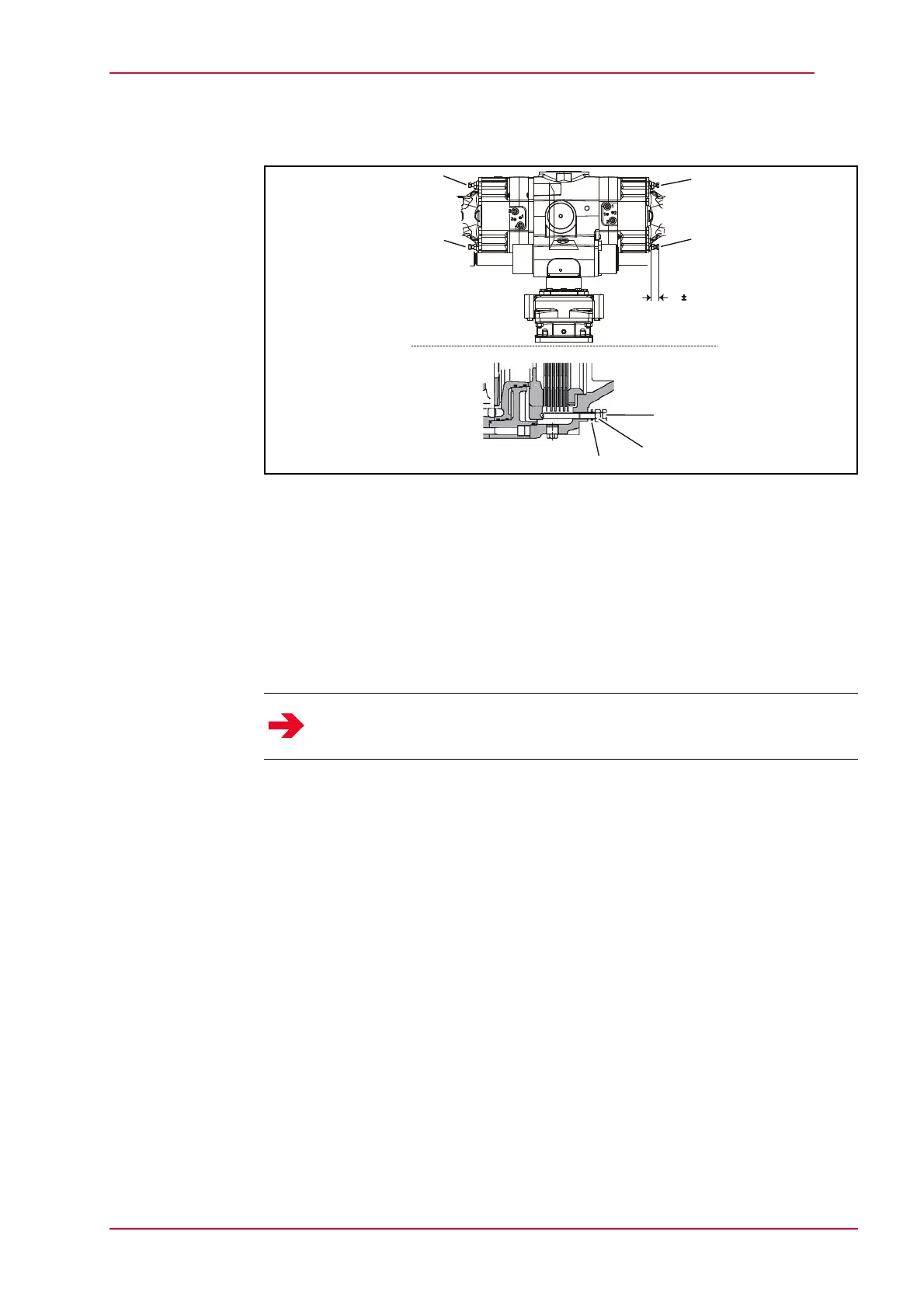
Fig. 8-4 Spring-loaded brake
1 Screw
2 Nut
3 Gasket
Loosen the nuts (2) and turn screws (1) by approx. 8 mm.
Tighten screws (1) in alternation with ring wrench, 1/4 rotation each, up to the
stop on the pressure plate.
Adjust spring-loaded brake after emergency release
Unscrew the screws (1) with nut (2) and gasket (3).
Replace gasket (3), grease or oil screw and reinstall.
Tighten the screws (1) until the adjustment dimension is 31 ± 0.5 mm.
Counterlock screws with nuts (2).
Check adjustment dimension again.
Notice
Screw in one rotation at maximum.
31 0,5
1
1
1
1
1
2
3