Setting 42, 43: Run and Direction Command for 2-Wire Sequence 2
Sets the drive for 2-Wire sequence 2.
When an input terminal programmed for 42 closes, the drive will operate in the selected direction. The drive will stop when
the input opens.
The input programmed for 43 selects the direction. If the input is open, forward direction is selected. If the input is closed,
reverse direction is selected.
Note: This function cannot be used simultaneously with settings 40 and 41.
Setting 44, 45, 46: Offset Frequency 1, 2, 3
These inputs add offset frequencies d7-01, d7-02, and d7-03 to the frequency reference. Refer to d7-01 to d7-03: Offset
Frequency 1 to 3 on page 73 for details.
Setting 47: Node Setup
If the S1-S3 option card is connected, closing this terminal sets a node address for operation on a CANopen network.
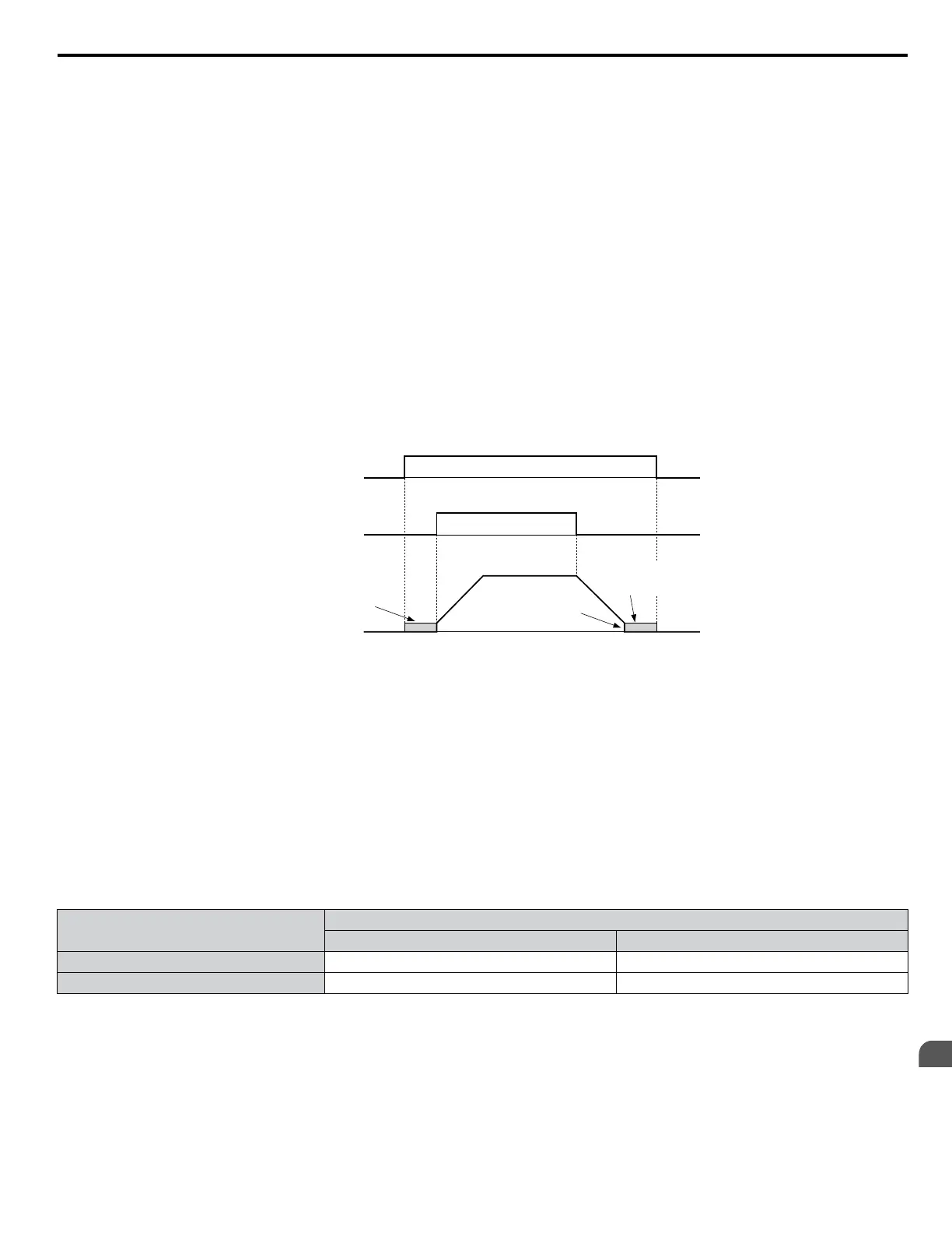
Setting 60: DC Injection Braking Command
DC Injection Braking is activated when a DC Injection Braking command is input while the drive is stopped. DC Injection
Braking is released when a Run command or a Jog command is input. Refer to b2: DC Injection Braking and Short Circuit
Braking on page 25 for details on setting up the DC Injection Braking function.
The diagram below illustrates DC Injection Braking:
DC Injection braking
command
FWD Run command
Output frequency
DC Injection
braking
DC Injection
braking
DC Injection Braking
Start Frequency
(b2-01)
OFF
OFF OFF
OFFON
ON
Figure 1.61 DC Injection Braking Input Timing Diagram
Setting 61, 62: External Speed Search Command 1, 2
These input functions enable Speed Search even if parameter b3-01 = 0 (no Speed Search at start). Refer to Speed Search
Activation on page 29 for details on how to use the input signals. Refer to b3: Speed Search on page 27 for more about Speed
Search.
Note: Simultaneously assigning Speed Search 1 and Speed Search 2 to the input terminals will trigger an oPE03 error.
Setting 63: Field Weakening
Enabled in V/f Control. When this input is closed, Field Weakening is performed. For details, see d6: Field Weakening and
Field Forcing.
Setting 65, 66: KEB Ride-Thru 1 (N.C.), 2 (N.O.)
Enables the KEB Ride-Thru. Refer to KEB Ride-Thru Function on page 135 for more information on this function.
DIgital Input Function
Drive Operation
Input Open Input Closed
Setting 65 (N.C.) KEB Ride-Thru Deceleration Normal operation
Setting 66 (N.O.) Normal operation KEB Ride-Thru Deceleration
Note: Simultaneously assigning KEB Ride-Thru 1 and KEB Ride-Thru 2 to the input terminals will trigger an oPE03 error.
Setting 67: Communication Test Mode
The drive has a built-in function to self-diagnose serial communications operation. The test involves wiring the send and
receive terminals of the RS-485/422 port together. The drive transmits data and then confirms that the communications are
received normally.
1.7 H: Terminal Functions
YASKAWA ELECTRIC SIEP YEAHHP 01B YASKAWA AC Drive – A1000 HHP Programming Manual
103
1
Parameter Details

 Loading...


