Output Voltage
Output Voltage
0 V
5 V
10 V
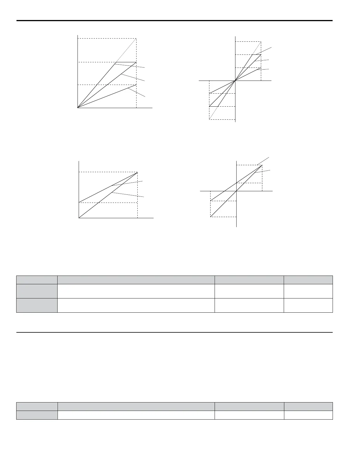
Gain 150%
Bias 0%
Gain = 150%
Bias = 0%
Gain = 100%
Bias = 0%
Gain = 50%
Bias = 0%
Gain 100%
Bias 0%
Gain 50%
Bias 0%
100%
Monitor Value
Monitor Value
0%
H4-07, 08 = 0 H4-07, 08 = 1
10 V
-10 V
100%
5 V
15 V
-5 V
-15 V
-100%
Figure 1.80 Analog Output Gain and Bias Setting Example 1 and 2
Set H4-03 to 30% for an output signal of 3 V at terminal FM when the monitored value is at 0%.
Gain = 100%
Bias = 30%
Gain = 100%
Bias = 0%
Gain 100%
Bias 30%
Gain 100%
Bias 0%
Monitor Value
Monitor Value
0 V
3 V
10 V
100%0%
Output Voltage
Output Voltage
H4-07, 08 = 0 H4-07, 08 = 1
10V
-10 V
100%
3 V
-4 V
-100%
Figure 1.81 Analog Output Gain and Bias Setting Example 3
n
H4-07, H4-08: Multi-Function Analog Output Terminal FM, AM Signal Level Selection
Sets the voltage output level of U parameter (monitor parameter) data to terminal FM and terminal AM using parameters
H4-07 and H4-08.
No. Name Setting Range Default
H4-07
Multi-Function Analog Output Terminal FM
Signal Level Selection
0 to 1 0
H4-08
Multi-Function Analog Output Terminal AM
Signal Level Selection
0 to 1 0
Setting 0: 0 to 10 V
Setting 1: -10 V to 10 V
u
H5: MEMOBUS/Modbus Serial Communication
Serial communication is possible in the drive using the built-in RS-422/485 port (terminals R+, R-, S+, S-) and programmable
logic controllers (PLCs) or similar devices running the MEMOBUS/Modbus protocol.
The H5-ooparameters set the drive for MEMOBUS/Modbus Communications.
n
H5-01: Drive Slave Address
Sets the drive slave address used for communications.
Note: Cycle the power after changing this parameter to enable the new setting.
No. Name Setting Range Default
H5-01 Drive Slave Address
0 to FFH
<1>
1FH
<1> If the address is set to 0, no response will be provided during communications.
1.7 H: Terminal Functions
122
YASKAWA ELECTRIC SIEP YEAHHP 01B YASKAWA AC Drive – A1000 HHP Programming Manual

 Loading...


