No. Name Setting Range Default
L6-09 Mechanical Weakening Detection Speed Level -110.0 to 110.0% 110%
n
L6-10: Mechanical Weakening Detection Time
Sets the time permitted for the situation selected in parameter L6-08 to arise before detecting mechanical weakening.
No. Name Setting Range Default
L6-10 Mechanical Weakening Detection Time 0.0 to 10.0 s 0.1 s
n
L6-11: Mechanical Weakening Detection Start Time
Sets the cumulative drive operation time at which Mechanical Weakening Detection is activated. The function activates when
U4-01 reaches the L6-11 value.
No. Name Setting Range Default
L6-11 Mechanical Weakening Detection Start Time 0 to 65535 h 0 h
u
L7: Torque Limit
The torque limit function limits the torque in each of the four quadrants individually to protect machinery in OLV, CLV,
AOLV/PM, and CLV/PM control modes. Set the limit through parameters, analog inputs, or by switching a digital output
programmed for “During torque limit” (H2-01, H2-02, H2-03 = 30) when the drive is operating at the torque limit.
n
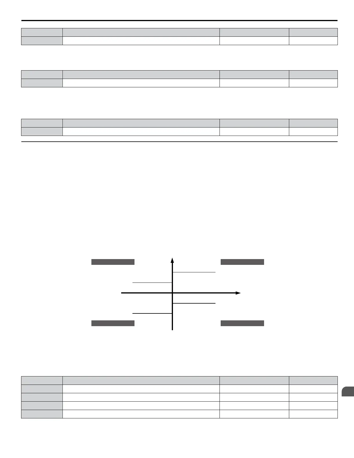
Setting Torque Limits
Parameters L7-01 to L7-04 define the torque limits for each of the four operation quadrants. it is also possible to use Analog
inputs to define a general limit for all operation conditions (H3-02, H3-06, H3-10 = 15) or to set separate limits for each
operation condition (H3-02, H3-06, H3-10 = 10, 11, or 12). Figure 1.104 shows limit setting is applied in each quadrant.
If two limit values are defined for the same operation conditions, the drive will use the lower value.
Note: The maximum output torque is ultimately limited by the drive output current (max. 150% of drive rated current in HD, 120% in ND). Output
torque will not exceed the drive rated current limit even if the torque limits are set to higher values.
Example: If parameter L7-01 = 130%, L7-02 to L7-04 = 200%, and an analog input sets a general torque limit of 150% (H3-02,
H3-06, H3-10 = 15), then the torque limit will be 130% in quadrant 1, but 150% in the other quadrants.
Positive torque reference
10: Positive Torque Limit
12: Regenerative Torque Limit
15: Torque Limit
Parameter L7-04
REV motor rotation
11: Negative Torque Limit
15: Torque Limit
Parameter L7-02
10: Positive Torque Limit
15: Torque Limit
Parameter L7-01
FWD motor rotation
11: Negative Torque Limit
12: Regenerative Torque Limit
15: Torque Limit
Parameter L7-03
Quadrant 2
Quadrant 3
Quadrant 1
Quadrant 4
REV run regenerative
REV run motoring
FWD run motoring
FWD run regenerative
Negative torque reference
Figure 1.104 Torque Limit Parameters and Analog Input Settings
n
L7-01 to L7-04: Torque Limits
These parameters set the torque limits in each quadrant.
No. Name Setting Range Default
L7-01 Forward Torque Limit 0 to 300% 200%
L7-02 Reverse Torque Limit 0 to 300% 200%
L7-03 Forward Regenerative Torque Limit 0 to 300% 200%
L7-04 Reverse Regenerative Torque Limit 0 to 300% 200%
Note: If the multi-function analog input is programmed for “10: Forward torque limit”, “11: Reverse torque limit”, “12: Regenerative torque
limit”, or “15: General torque limit”, the drive uses the lowest value from L7-01 through L7-04, or analog input torque limit.
1.8 L: Protection Functions
YASKAWA ELECTRIC SIEP YEAHHP 01B YASKAWA AC Drive – A1000 HHP Programming Manual
151
1
Parameter Details

 Loading...


