No.
(Addr.
Hex)
Name Description
Analog Output
Level
Unit
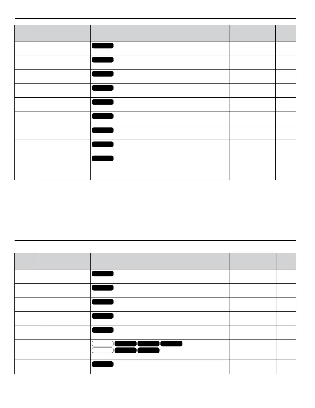
U1-21
(77)
AI-A3 Terminal V1 Input
Voltage Monitor
All Modes
Displays the input voltage to terminal V1 on analog input card AI-A3.
10 V: 100% 0.1%
U1-22
(72A)
AI-A3 Terminal V2 Input
Voltage Monitor
All Modes
Displays the input voltage to terminal V2 on analog input card AI-A3.
10 V: 100% 0.1%
U1-23
(72B)
AI-A3 Terminal V3 Input
Voltage Monitor
All Modes
Displays the input voltage to terminal V3 on analog input card AI-A3.
10 V: 100% 0.1%
U1-24
(7D)
Input Pulse Monitor
All Modes
Displays the frequency to pulse train input terminal RP.
Determined by H6-02 1 Hz
U1-25
(4D)
Software Number of
Master CPU (Flash)
All Modes
FLASH ID: Software number of Master CPU
No signal output
available
–
U1-26
(5B)
Software No. of Slave
CPU (ROM)
All Modes
ROM ID: Software number of Slave CPU
No signal output
available
–
U1-27
(7A8)
MessageID (OPR)
All Modes
Factory use
No signal output
available
–
U1-28
(7A9)
MessageID (INV)
All Modes
Factory use
No signal output
available
–
U1-29
(7AA)
Software No. (PWM)
All Modes
PWM ID: Software No. of slave or inverter module axis processors
Note: This parameter is only available in models CIMR-
Ao4A0930, 4A1200, and A1000 HHP.
No signal output
available
–
<1> The number of decimal places in the parameter value depends on the drive model and the ND/HD selection in parameter C6-01. This value has two
decimal places (0.01 A) if the drive is set for a maximum applicable motor capacity up to and including 11 kW, and one decimal place (0.1 A) if
the maximum applicable motor capacity is higher than 11 kW.
<2> When reading the value of this monitor via MEMOBUS/Modbus, a value of 8192 is equal to 100% of the drive rated output current.
<3> Values shown are specific to 400 V class drives. Multiply the value by 1.4375 for 575 V class drives. Multiply the value by 1.725 for 690 V class
drives.
<4> The display resolution depends on the ND/HD selection in parameter C6-01. This value has two decimal places (0.01 kW) if the drive is set for a
maximum applicable motor capacity up to and including 11 kW, and one decimal place (0.1 kW) if the maximum applicable motor capacity is
higher than 11 kW.
u
U2: Fault Trace
No.
(Addr.
Hex)
Name Description
Analog Output
Level
Unit
U2-01
(80)
Current Fault
All Modes
Displays the current fault.
No signal output
available
–
U2-02
(81)
Previous Fault
All Modes
Displays the previous fault.
No signal output
available
–
U2-03
(82)
Frequency Reference at
Previous Fault
All Modes
Displays the frequency reference at the previous fault.
No signal output
available
0.01 Hz
U2-04
(83)
Output Frequency at
Previous Fault
All Modes
Displays the output frequency at the previous fault.
No signal output
available
0.01 Hz
U2-05
(84)
Output Current at Previous
Fault
All Modes
Displays the output current at the previous fault.
No signal output
available
<1>
<2>
U2-06
(85)
Motor Speed at Previous
Fault
V/f
OLV/PM
V/f w PG
AOLV/PM
OLV
CLV/PM
CLVV/f w PG
AOLV/PM
OLV
CLV/PM
CLVV/f
OLV/PM
V/f w PG
AOLV/PM
OLV
CLV/PM
CLVV/f w PG
AOLV/PM
OLV
CLV/PM
CLV
Displays the motor speed at the previous fault.
No signal output
available
0.01 Hz
U2-07
(86)
Output Voltage at
Previous Fault
All Modes
Displays the output voltage at the previous fault.
No signal output
available
0.1 Vac
A.15 U: Monitors
300
YASKAWA ELECTRIC SIEP YEAHHP 01B YASKAWA AC Drive – A1000 HHP Programming Manual

 Loading...


